| Icon
|
Name
|
Topic
|
Description
|
Author
|
Code
|
|
|
![]()
|
ArchTextures
|
Architecture and construction
|
It allows you to add basic, non-photorealistic textures to architectural objects created with the Arch Workbench.
|
furti
|
https://github.com/furti/FreeCAD-ArchTextures
|
![]()
|
![]()
|
BCFPlugin
|
Architecture and construction
|
It aims to support the BIM Collaboration Format (BCF).
|
podestplatz
|
https://github.com/podestplatz/BCF-Plugin-FreeCAD
|
![]()
|
|
![]()
|
BIM
|
Architecture and construction
|
It aims to implement a complete building information modeling (BIM) workflow in FreeCAD.
It extends the Arch Workbench, and gathers tools from other workbenches to provide an environment that is convenient to model buildings, and work with IFC files.
|
yorikvanhavre
|
https://github.com/yorikvanhavre/BIM_Workbench
|
![]()
|
|
![]()
|
BIMBots
|
Architecture and construction
|
It allows you to upload a FreeCAD model or selected parts of a FreeCAD model to a BIMBots instance (usually a BIMServer with external services enabled), and perform different services and analyses on your model, and read the results in FreeCAD, usually under the form of a text report, or a BCF file.
|
BIMBots
|
https://github.com/opensourceBIM/BIMbots-FreeCAD
|
![]()
|
|
![]()
|
Dodo
|
Architecture and construction
|
It provides tools to create frames (trusses, beams) and pipelines (tubes, elbows, flanges), and query those objects.
This is the new version of Flamingo, intended for Python 3 and Qt5.
|
oddtopus
|
https://github.com/oddtopus/dodo
|
![]()
|
|
![]()
|
Flamingo
|
Architecture and construction
|
It provides tools to create frames (trusses, beams) and pipelines (tubes, elbows, flanges), and query those objects.
This is the old version of Dodo, intended for Python 2 and Qt4.
You should prefer Dodo for new models.
|
oddtopus
|
https://github.com/oddtopus/flamingo
|
![]()
|
![]()
|
|
|
GeoData
|
Architecture and construction
|
It provides tool to import geographical information from a given point on Earth by its latitude and longitude, of from OpenStreetMap, Google Maps, Bing Map, or Here Map.
|
microelly2
|
https://github.com/microelly2/geodata
|
|
![]()
|
![]()
|
Geomatics
|
Architecture and construction
|
It is partially based on the GeoData.
It provides functionality specific to Geomatics or Survey engineering, including importing point files, creating surfaces, creating contours, and creating sections.
This is partially migrated to the Trails workbench.
|
HakanSeven12
|
https://github.com/HakanSeven12/FreeCAD-Geomatics-Workbench
|
![]()
|
![]()
|
![]()
|
OSE Piping
|
Architecture and construction
|
Create different piping fittings.
It supports Flamingo.
|
Ruslan
|
https://github.com/rkrenzler/ose-piping-workbench
|
![]()
|
|
![]()
|
Reinforcement
|
Architecture and construction
|
It provides tools for Reinforcement Generation and Detailing.
This workbench provides an interface and presets for the creation of common rebar types.
And tools to generate rebars bill of material, rebar shape cut list, bar bending schedule, and rebars drawing and dimension.
|
amrit3701
|
https://github.com/amrit3701/FreeCAD-Reinforcement
|
![]()
|
|
|
|
SteelColumn
|
Architecture and construction
|
It provides tools for creating complex steel columns assembled from IPE profiles and plates.
|
ebrahimraeyat
|
https://github.com/ebrahimraeyat/momen
|
![]()
|
|
![]()
|
Timber
|
Architecture and construction
|
It provides tools to facilitate the design and modeling of wood-frame and structural walls.
This workbench is no longer developed nor maintained by its author.
|
j-wiedemann
|
https://github.com/j-wiedemann/FreeCAD-Timber
|
![]()
|
![]()
|
![]()
|
Trails
|
Architecture and construction
|
It provides functionality specific to transportation engineering (roads and rail).
It includes components to perform analysis of curvature.
|
joelgraff
|
https://github.com/joelgraff/freecad.trails
|
![]()
|
|
![]()
|
Wood Frame
|
Architecture and construction
|
It provides tools to facilitate the design and modelling of wood-frame and structural walls, as well as cut lists for beams.
|
JeromeL63
|
https://github.com/JeromeL63/Wood-Frame
|
|
![]()
|
![]()
|
A2plus
|
Assembly
|
It provides tools to create multi-part assemblies.
It is a fork and extension of the older Assembly2 Workbench, but it is not compatible with it.
|
kbwbe
|
https://github.com/kbwbe/A2plus
|
![]()
|
|
![]()
|
Assembly2
|
Assembly
|
It provides tools to create multi-part assemblies.
It is unmaintained since 2016.
Consider using A2plus instead.
|
hamish2014
|
https://github.com/hamish2014/FreeCAD_assembly2
|
![]()
|
![]()
|
![]()
|
Assembly3
|
Assembly
|
It is used to perform assembly of different bodies contained in a single file or in multiple documents.
It was a testbed for the App Link object that was eventually included in the master code.
It is the most complex solution and supports things like interactive kinematics.
|
realthunder
|
https://github.com/realthunder/FreeCAD_assembly3
|
|
|
![]()
|
Assembly4
|
Assembly
|
It is a solution based on the enhanced expression engine and the App Link object developed in the branch of Assembly3.
Assembly4 does not work with a proper constraint solver, instead it uses the expression engine to position bodies with respect to Local Coordinate Systems (LCS).
|
Zolko
|
https://github.com/Zolko-123/FreeCAD_Assembly4
|
![]()
|
|
|
|
Autoload
|
Customization
|
It is a small extension that allows you to select the workbenches that should be loaded when you start FreeCAD.
It can be used in combination with other extensions from the same author such as CommandPanel, PieMenu, and ShortCuts.
|
triplus
|
https://github.com/triplus/Autoload
|
![]()
|
|
|
|
CommandPanel
|
Customization
|
It is an extension that provides a panel that can be used store tools from different workbenches.
|
triplus
|
https://github.com/triplus/CommandPanel
|
![]()
|
|
|
|
CubeMenu
|
Customization
|
CubeMenu provides the ability to manage the FreeCAD navigation cube menu structure and overall appearance.
|
triplus
|
https://github.com/triplus/CubeMenu
|
![]()
|
|
|
|
Glass
|
Customization
|
It is an extension that shows the combo view (tree view and property editor) as a transparent overlay over the 3D view.
|
triplus
|
https://github.com/triplus/Glass
|
![]()
|
|
|
|
IconThemes
|
Customization
|
It is an extension that provides the ability of changing the icons of the default program.
Icon sets aren't provided with this extension; these need to be provided separately.
|
triplus
|
https://github.com/triplus/IconThemes
|
![]()
|
|
|
|
Launcher
|
Customization
|
It is a small extension that provides a dedicated dialog box to search and launch commands.
Instead of clicking on a toolbar button or menu entry, this method of executing commands may be faster for some users.
|
triplus
|
https://github.com/triplus/Launcher
|
![]()
|
|
![]()
|
ModernUI
|
Customization
|
Replaces the standard user interface (UI) with feature such as ribbon menus and collapsing/expanding panels on mouse-over.
|
HakanSeven12
|
https://github.com/HakanSeven12/Modern-UI
|
![]()
|
|
|
|
NavigationIndicator
|
Customization
|
It is an extension that adds an indicator for the mouse navigation style in the status bar.
Since FreeCAD 0.17 this extension is obsolete, as the indicator is included natively in FreeCAD.
|
triplus
|
https://github.com/triplus/NavigationIndicator
|
![]()
|
![]()
|
|
|
PersistentToolbars
|
Customization
|
It is a small extension to keep the toolbars in their locations.
Since FreeCAD 0.17 this extension is obsolete, as the functionality is included natively in FreeCAD.
|
triplus
|
https://github.com/triplus/PersistentToolbars
|
![]()
|
![]()
|
|
|
PieMenu
|
Customization
|
It is a small extension that shows a pie menu to select tools or commands when the Tab key is pressed.
A pie menu is an interface that appears in Blender and other systems like Android mobile phones to launch commands.
|
triplus
|
https://github.com/triplus/PieMenu
|
![]()
|
|
|
|
Pluginloader
|
Customization
|
It is a small extension that allows the user to install macros, external workbenches, and other extensions in FreeCAD.
Since FreeCAD 0.17 this utility is obsolete, as this functionality is already provided by the Addon Manager.
|
microelly2
|
https://github.com/microelly2/freecad-pluginloader
|
![]()
|
![]()
|
|
|
RemBench
|
Customization
|
It is a small extension that remembers and automatically activates a workbench based on the document tab that is selected.
|
triplus
|
https://github.com/triplus/RemBench
|
![]()
|
|
![]()
|
SearchBar
|
Customization
|
It is an extension that adds a search bar next to the what's this? tool.
The search results include tools, objects and preferences.
Other mods can extend it by registering a result provider.
|
Suzanne Soy
|
https://github.com/SuzanneSoy/SearchBar
|
|
|
|
|
SelectorToolbar
|
Customization
|
It is a small extension that provides a point and click experience for switching workbenches.
|
triplus
|
https://github.com/triplus/SelectorToolbar
|
![]()
|
|
|
|
ShortCuts
|
Customization
|
It is a small extension that provides a manager and overlay for shortcuts.
|
triplus
|
https://github.com/triplus/ShortCuts
|
![]()
|
|
|
|
TabBar
|
Customization
|
It is a small extension that adds a window with tabs in order to select workbenches.
|
triplus
|
https://github.com/triplus/TabBar
|
![]()
|
|
|
|
ToolbarStyle
|
Customization
|
It is a small extension that allows the configuration of toolbars, with icons, text, or both.
|
triplus
|
https://github.com/triplus/ToolbarStyle
|
![]()
|
|
![]()
|
MOOC
|
Education
|
It provides an interactive tutorial to learn about FreeCAD directly inside the program.
It allows you to evaluate your self-learning.
|
rockn
|
https://framagit.org/freecad-france/mooc-workbench
|
![]()
|
|
![]()
|
AirPlaneDesign
|
Engineering
|
It is an experimental workbench to design wings and airplane objects.
|
FredsFactory (a179308)
|
https://github.com/FredsFactory/FreeCAD_AirPlaneDesign
|
![]()
|
|
|
|
FreeCADTools
|
Engineering
|
It contains tools to create metal profiles, square tubing, z profile, palette, rotation, drawing, and more.
|
Siardeni
|
https://github.com/Siardeni/FreeCADTools
|
|
|
![]()
|
GDML
|
Engineering
|
It contains tools to handle the Geometry Definition Markup Language (GDML).
|
KeithSloan
|
https://github.com/KeithSloan/GDML
|
![]()
|
|
![]()
|
GDT
|
Engineering
|
It is a collection of tools to add geometric dimensioning and tolerancing (GDT) labels in 2D and 3D technical drawings.
It implements the standard ISO 16792.
|
juanvanyo
|
https://github.com/juanvanyo/FreeCAD-GDT
|
![]()
|
![]()
|
![]()
|
Glider
|
Engineering
|
It contains tools to design paragliders and kites using the OpenGlider library.
|
booya
|
https://github.com/booya-at/OpenGlider
|
|
|
![]()
|
KicadStepUp
|
Engineering
|
It is aimed at helping both KiCad and FreeCAD users in collaborating with electrical (ECAD) and mechanical (MCAD) design.
With FreeCAD it's possible to design a printed circuit board, and push it to KiCad; alternatively, the board can be designed in KiCad, it can be imported by FreeCAD, it can be edited with the Sketcher Workbench, and pushed back into KiCad.
The 3D model, boards and enclosure, can be exported to VRML with materials properties for use in KiCad or Blender.
|
easyw
|
https://github.com/easyw/kicadStepUpMod
|
![]()
|
|
![]()
|
LCInterlocking
|
Engineering
|
It contains tools to create interlocking parts that can be cut with laser-cutters.
Tabs and hinges can be added, and the sketch can be exported to SVG.
|
execuc
|
https://github.com/execuc/LCInterlocking
|
![]()
|
|
|
|
Maker Workbench
|
Engineering
|
The Maker Workbench is composed of a mechatronic components system and an optic components system.
The user can modify these components to customize their own system.
|
David Muñoz
|
https://github.com/URJCMakerGroup/MakerWorkbench
|
![]()
|
|
![]()
|
OSE 3D Printer
|
Engineering
|
A workbench for designing 3D printers by Open Source Ecology for Distributive Enterprise.
|
G Roques
|
https://github.com/gbroques/ose-3d-printer-workbench
|
![]()
|
|
![]()
|
Pyrate
|
Engineering
|
It is used to design optical lenses.
The project aims to provide an optical raytracer for isotropic, homogeneous anisotropic and inhomogeneous isotropic GRIN media.
|
mess42, joha2
|
https://github.com/mess42/pyrate
|
![]()
|
|
![]()
|
Rocket
|
Engineering
|
It provides tools for model and amateur rocket design.
Users can quickly and easily create rocket components suitable for 3D printing, CNC milling, or laser cutting
|
DavesRocketShop
|
https://github.com/davesrocketshop/Rocket.git
|
![]()
|
|
![]()
|
SheetMetal
|
Engineering
|
It provides tools to design an object made of a folded sheet, such as a metal case or enclosure.
The user starts with a flat sheet, then uses tools to extrude and bend the faces of the object until the desired shape is obtained.
The body may then be unfolded to obtain the required flat material, and to use as input for mills or laser cutting machines.
|
Shai Seger and Ulrich Brammer
|
https://github.com/shaise/FreeCAD_SheetMetal
|
![]()
|
|
![]()
|
Ship
|
Engineering
|
It is used to create structures that are common to ships.
It currently is seeking a maintainer.
|
Jose Luis Cercós Pita
|
https://github.com/FreeCAD/freecad.ship
|
![]()
|
![]()
|
![]()
|
CADExchanger
|
Information and data
|
It is an extension that allows FreeCAD to import and export file formats supported by the commercial "CAD Exchanger" application, such as Rhino 3dm or ACIS sat, and mesh formats like OBJ and STL.
|
yorikvanhavre
|
https://github.com/yorikvanhavre/CADExchanger
|
![]()
|
|
|
|
dxf_library
|
Information and data
|
It installs the DXF Python importer and exporter.
This was required in FreeCAD versions v0.15 and below.
This is not needed anymore when using the built-in DXF importer in v0.16 and above.
This library is still needed if you wish to explicitly use the Python importer, or if you wish to export directly from the 3D model.
Please notice that the built-in importer is faster than the Python importer, but in many cases the Python importer produces better results.
|
yorikvanhavre
|
https://github.com/yorikvanhavre/Draft-dxf-importer
|
![]()
|
|
![]()
|
DynamicData
|
Information and data
|
It is an extension that allows creating container objects to hold custom properties of any type that FreeCAD supports, for example, length or placement.
These custom properties can then be used in mathematical expressions just like other properties in the Sketcher Workbench or Spreadsheet Workbench.
|
mwganson
|
https://github.com/mwganson/DynamicData
|
![]()
|
|
![]()
|
InventorLoader
|
Information and data
|
It is an extension designed to import Autodesk Inventor files.
Currently only Parts (IPT) can be displayed, not assemblies (IAM) nor drawings (IDW).
As Inventor files contain a complete ACIS model representation, SAT and SAB files can also be imported.
Export will not be supported, neither to IPT nor to SAT.
|
jmplonka
|
https://github.com/jmplonka/InventorLoader
|
![]()
|
|
![]()
|
ImportNURBS
|
Information and data
|
A workbench to add support for importing 3dm files using open rhino3dm library Noteː This workbench is still under development
|
keithsloan52
|
https://github.com/KeithSloan/ImportNURBS
|
![]()
|
|
![]()
|
Plot
|
Information and data
|
It is a layer on top of the Matplotlib Python module to graph mathematical functions and vectors of points.
|
Jose Luis Cercós Pita
|
https://github.com/FreeCAD/freecad.plot
|
![]()
|
|
![]()
|
Reporting
|
Information and data
|
It adds tools to extract information from a FreeCAD document using SQL statements, and show the results in a spreadsheet.
The SQL statements can be used from a graphical user interface or from Python scripts.
It works in a similar way to the Arch Schedule tool but is more powerful due to the flexibility that SQL provides.
|
furti
|
https://github.com/furti/FreeCAD-Reporting
|
![]()
|
|
![]()
|
WebTools
|
Information and data
|
It contains a series of tools to communicate with web services like Git, a BIM server, and Sketchfab.
|
yorikvanhavre
|
https://github.com/yorikvanhavre/WebTools
|
![]()
|
|
![]()
|
YAML
|
Information and data
|
It is an extension that adds an importer to load and manipulate objects from YAML files.
In this way it's easier to design and check 3D parts before manufacturing.
|
Mambix
|
https://github.com/Mambix/FreeCAD-yaml-workspace
|
![]()
|
|
|
|
3DfindIT
|
Parts
|
3DfindIT.com, the engineering search engine for 3D components from CADENAS, provides users with easy access to millions of CAD models from thousands of international manufacturers and a range of intuitive search methods.
|
tsielaff, berndhahnebach
|
https://github.com/cadenasgmbh/3dfindit-freecad-integration
|
![]()
|
|
![]()
|
BOLTSFC
|
Parts
|
It is an extension that allows you to use the BOLTS "Open Library for Technical Specifications", which is a collection of objects like nuts, screws, bolts, and so on, parametrically defined.
|
jreinhardt, berndhahnebach
|
https://github.com/berndhahnebach/BOLTSFC
|
![]()
|
|
![]()
|
CadQuery
|
Parts
|
It allows users to design parametric 3D CAD models defined by the CadQuery CAD scripting API.
It includes a full-featured editor with auto-completion, syntax highlighting, line numbering, and code folding.
Example scripts are included.
Script variables can be edited dynamically through the use of a parameter dialog.
This workbench also includes cqparts, which is a library that adds support for parts and assemblies with constraints on top of CadQuery.
|
jmwright
|
https://github.com/jmwright/cadquery-freecad-module
|
![]()
|
|
![]()
|
Fasteners Workbench
|
Parts
|
It is a workbench that provides various fasteners, screws, bolts, nuts, etc., to attach to your model complying with ISO standards.
|
Ulrich Bramar (@ulrich1a) and Shai Seger (@shais)
|
https://github.com/shaise/FreeCAD_FastenersWB
|
![]()
|
|
![]()
|
FCGear
|
Parts
|
It is an extension that adds many different gears like cylindric involute, involute rack, cylindric cycloid, spherical involute bevel-gear, and crown gear.
|
looooo
|
https://github.com/looooo/freecad.gears
|
![]()
|
|
|
|
Frametools
|
Parts
|
It is an extension with tools to create frames and beams, including two intersecting beams, in which one beam is cut by a plane or by another beam.
|
looooo
|
https://github.com/looooo/freecad.frametools
|
![]()
|
|
|
|
Parts Library
|
Parts
|
It is an extension that downloads a library of parts in STEP format .step or in FreeCAD format .FCStd that can be imported into a document.
Users can contribute content to this library by forking the repository, adding their own parts under a permissive CC-BY 3.0 license, and submitting a pull request to merge the new objects.
|
Community
|
https://github.com/FreeCAD/FreeCAD-library
|
![]()
|
|
|
|
PCB
|
Parts
|
It is a workbench that allows the user to import and create printed circuit boards (PCB) in FreeCAD.
It supports layers, colors, transparencies, importing Step and Iges models, and displaying holes and vias.
|
marmni
|
https://github.com/marmni/FreeCAD-PCB
|
![]()
|
|
|
|
Retr3d
|
Parts
|
It is a framework designed to model and manufacture 3D printable parts starting from electronic waste.
The intention of this project is to recycle e-waste, and promote 3D printing, especially in developing economies.
|
Maaphoo
|
https://github.com/Maaphoo/Retr3d
|
![]()
|
|
|
|
Stemfie Workbench
|
Parts
|
It is a workbench that generates a set of parametric parts for the Stemfie Project.
|
Stemfie Community
|
https://github.com/bilbaomakers/StemfieWB
|
|
|
|
|
Symbols Library
|
Parts
|
It is an extension that downloads a library of SVG symbols that can be used in FreeCAD, particularly in the TechDraw Workbench to produce technical documentation.
Users can contribute content to this library by forking the repository, adding their own symbols under a permissive CC-BY 3.0 license, and submitting a pull request to merge the new objects.
|
Community
|
https://github.com/FreeCAD/FreeCAD-symbols
|
![]()
|
|
![]()
|
ThreadProfile
|
Parts
|
It provides tools to create parametric 2D thread profiles compatible with extrusion tools in Part and PartDesign workbenches.
|
mwganson
|
https://github.com/mwganson/ThreadProfile
|
![]()
|
|
|
|
Pivy_trackers
|
Programming
|
Pivy_trackers provides a Python developer with an easy way to directly manipulate the Coin3D scenegraph by generating specific scenegraph node structures which are then inserted and accessed though the pivy_tracker classes.
|
joelgraff
|
https://github.com/joelgraff/pivy_trackers
|
![]()
|
|
![]()
|
Animation
|
Pseudo-assembly
|
It contains many tools to simulate movement of parts, create sequences of pictures, and thus produce an animation.
The position and rotation of objects can be changed at different times, but also other properties like visibility, transparency, shape color, and camera position.
|
microelly2
|
https://github.com/microelly2/Animation
|
![]()
|
![]()
|
![]()
|
ExplodedAssembly
|
Pseudo-assembly
|
It allows creating exploded views and animations of assemblies.
It was previously known as "ExplodedAnimation".
|
JMG1
|
https://github.com/JMG1/ExplodedAssembly
|
![]()
|
|
![]()
|
Lattice2
|
Pseudo-assembly
|
It provides tools for working with placements and arrays of placements.
It is a sort of assembly workbench but there are no constraints nor relationships.
Instead, the workbench focuses in arrays of placements that can be generated, combined, transformed, superimposed, and populated with shapes.
It can also create exploded assemblies.
|
DeepSOIC
|
https://github.com/DeepSOIC/Lattice2
|
![]()
|
|
![]()
|
Manipulator
|
Pseudo-assembly
|
It is aimed at helping users in aligning, moving, rotating, and measuring 3D objects through a friendly graphical interface.
|
easyw
|
https://github.com/easyw/Manipulator
|
![]()
|
|
![]()
|
Part-o-magic
|
Pseudo-assembly
|
It is an experimental workbench that provides some improvements to Std Part and PartDesign Body containers (automatic grouping, visibility automation, etc.), in order to work with documents that have multiple parts with deep feature hierarchies.
It provides a Body-like container for the Part Workbench, and for other workbenches that produce solid shapes.
Part-o-magic does not provide assembly constraints, but the tools included may be useful in conjunction with a true assembly workbench.
|
DeepSOIC
|
https://github.com/DeepSOIC/Part-o-magic
|
![]()
|
|
![]()
|
Workfeature
|
Pseudo-assembly
|
It provides tools to produce different points, axes, and planes, in order to facilitate the creation of assemblies.
This workbench is based on the older Workfeatures macro, which was hosted in the macros recipes page.
Currently, the macro has a bit more functionality than the workbench, but eventually the workbench will integrate all existing tools of the macro.
They also differ in the graphical user interface; the macro creates a panel next to the tree view and the task panel, while the workbench provides its tools in toolbars, just like other workbenches.
|
Rentlau
|
https://github.com/Rentlau/WorkFeature-WB
|
![]()
|
|
|
|
Kerkythea
|
Rendering
|
It adds a simple exporter to produce XML files for use with the Kerkythea freeware renderer.
|
marmni
|
https://github.com/marmni/FreeCAD-Kerkythea/blob/master/exportToKerkythea.FCMacro
|
![]()
|
|
![]()
|
POV-Ray-Rendering
|
Rendering
|
It creates renderings of your FreeCAD model and is very easy to use but also offers all options for advanced users.
|
The_Raytracers
|
https://github.com/TheRaytracers/freecad-povray-render
|
![]()
|
|
![]()
|
Render
|
Rendering
|
It can produce high-quality rendered images, using open-source external rendering engines like Pov-ray, Luxrender, and Appleseed.
Render is a replacement for the Raytracing Workbench, and uses the same templates so they are compatible.
In the future Render may also support Kerkythea, Blender's EEVEE, and OpenCascade's CadRays engines.
|
yorikvanhavre
|
https://github.com/FreeCAD/FreeCAD-render
|
![]()
|
|
![]()
|
3D Printing Tools
|
Shapes
|
It has tools to do small changes to meshes imported from external files like STL.
|
mark1791
|
https://github.com/mark1791/3D_Printing_Tools
|
![]()
|
|
|
|
Cura Engine
|
Shapes
|
It is an extension that integrates CuraEngine into FreeCAD in order to facilitate gcode generation for 3D printing.
This addon is unmaintained since 2014 and no longer works with recent versions of CuraEngine.
|
cblt2l
|
https://github.com/cblt2l/FreeCAD-CuraEngine-Plugin
|
![]()
|
![]()
|
![]()
|
CurvedShapes
|
Shapes
|
It has tools to create 3D curves from 2D profiles
|
chbergmann
|
https://github.com/chbergmann/CurvedShapesWorkbench
|
![]()
|
|
![]()
|
Curves
|
Shapes
|
It is a collection of tools to create and edit NURBS curves and surfaces.
|
tomate44 (Chris_G)
|
https://github.com/tomate44/CurvesWB
|
![]()
|
|
![]()
|
Defeaturing
|
Shapes
|
It provides tools to edit STEP objects to remove features like holes, faces, and edges, and perform some operations with the simplified objects.
|
easyw
|
https://github.com/easyw/Defeaturing_WB
|
![]()
|
|
![]()
|
Design456
|
Shapes
|
Direct modeling tools for FreeCAD.
|
Mariwan Jalal
|
https://github.com/MariwanJ/Design456
|
![]()
|
|
![]()
|
Drawing Dimensioning
|
Shapes
|
It adds dimensioning and annotation tools to the Drawing Workbench.
It is deprecated since FreeCAD 0.17.
Consider using TechDraw Workbench instead.
|
hamish2014
|
https://github.com/hamish2014/FreeCAD_drawing_dimensioning
|
![]()
|
![]()
|
![]()
|
Lithophane
|
Shapes
|
It is an extension to convert a provided image to a "lithophane" for 3D printing.
A lithophane is an image that can only be seen properly when illuminated from behind.
|
furti
|
https://github.com/furti/FreeCAD-Lithophane
|
![]()
|
|
![]()
|
MeshRemodel
|
Shapes
|
It provides tools to help re-create or re-model imported mesh objects to obtain a solid shape.
The workflow is to create points from the mesh's vertices, and use those to create sketches, which can then be extruded.
|
mwganson
|
https://github.com/mwganson/MeshRemodel
|
![]()
|
|
|
|
Nurbs
|
Shapes
|
It is a collection of scripts for managing freeform surfaces and curves.
|
microelly2
|
https://github.com/microelly2/freecad-nurbs
|
![]()
|
|
![]()
|
Pyramids and Polyhedrons Workbench
|
Shapes
|
It has tools for generating pyramids, regular polyhedra and geodesic speres, fully scalable and usable like regular bodies.
|
eddyverl
|
https://github.com/eddyverl/FreeCAD-Pyramids-and-Polyhedrons
|
|
|
|
|
Reconstruction
|
Shapes
|
It provides utilities to reconstruct models from images.
|
microelly2
|
https://github.com/microelly2/reconstruction
|
![]()
|
![]()
|
![]()
|
Silk
|
Shapes
|
It is a collection of NURBS surface modeling tools focused on low degree and seam continuity.
Silk is the new name of the NURBSlib-EVM project.
|
edwardvmills
|
https://github.com/edwardvmills/Silk
|
![]()
|
|
![]()
|
Slic3r-tools
|
Shapes
|
It allows exporting parts, and opening the resulting STL in Slic3r.
You can set up a default print profile, and directly get information about the resources that would be used to 3D print it, as well as quickly generate the .gcode file.
|
limikael
|
https://github.com/limikael/freecad-slic3r-tools
|
![]()
|
|
|
|
SlopedPlanesMacro
|
Shapes
|
It allows you to build figures controlling the slopes of the faces of objects.
|
Damian Caceres Moreno
|
https://github.com/luzpaz/SlopedPlanesMacro
|
![]()
|
|
![]()
|
Cfd
|
Simulation
|
It provides a graphical interface to the OpenFOAM solver to perform computational fluid dynamics (CFD) simulations.
|
qingfengxia
|
https://github.com/qingfengxia/Cfd
|
![]()
|
|
![]()
|
CfdOF
|
Simulation
|
It is a fork of the Cfd workbench that focuses on ease of use; it is intended for people who are just starting in the world of CFD and OpenFOAM.
|
jaheyns
|
https://github.com/jaheyns/CfdOF
|
![]()
|
|
![]()
|
DesignSPHysics
|
Simulation
|
It provides a graphical user interface to DualSPHysics, a fluid dynamics solver using the smoothed particle hydrodynamics (SPH) model.
|
ndrs92
|
https://github.com/DualSPHysics/DesignSPHysics
|
![]()
|
|
![]()
|
EM
|
Simulation
|
It provides a graphical interface for different solvers by FastFieldSolvers.
At present it supports the 3D magneto-quasistatic impedance solver FastHenry.
Support for the 3D electrostatic capacitance solver FasterCap is ongoing.
|
FastFieldSolvers S.R.L.
|
https://github.com/ediloren/EM-Workbench-for-FreeCAD
|
![]()
|
|
![]()
|
FEM FrontISTR
|
Simulation
|
It provides a graphical interface for FrontISTR, an open-source large-scale parallel FEM program for nonlinear structural analysis.
|
kinagaki
|
https://github.com/FrontISTR/FEM_FrontISTR
|
|
|
 You can leave the default path here, or change if you wish:
 No need to set the PYTHONPATH variable, unless you plan to do some advanced python programming, in which case you probably already know what this is for:
 During the installation, a couple of additional components, which are bundled inside the installer, will be installed too:
 That's it, FreeCAD is installed.
You will find it in your start menu.
That's it, FreeCAD is installed.
You will find it in your start menu.
 Installing a development version
Packaging FreeCAD and creating an installer takes some time and dedication, so usually development (also called pre-release) versions are provided as .zip (or .7z) archives.
These don't need to be installed; just unpack them and launch FreeCAD by double-clicking the FreeCAD.exe file that you will find inside.
This also allows you to keep both the stable and "unstable" versions together on the same computer.
Installing a development version
Packaging FreeCAD and creating an installer takes some time and dedication, so usually development (also called pre-release) versions are provided as .zip (or .7z) archives.
These don't need to be installed; just unpack them and launch FreeCAD by double-clicking the FreeCAD.exe file that you will find inside.
This also allows you to keep both the stable and "unstable" versions together on the same computer.
 Auto-load module: (General category, General tab) Normally, FreeCAD will start by showing you the start page.
You can skip this and begin a FreeCAD session directly in the workbench of your choice, listed under Startup, Auto load module after startup.
Workbenches will be explained in detail in the next chapter.
Create new document at startup: (General category, Document tab) Combined with the Auto-load module option above, if checked this starts FreeCAD ready for work.
Auto-load module: (General category, General tab) Normally, FreeCAD will start by showing you the start page.
You can skip this and begin a FreeCAD session directly in the workbench of your choice, listed under Startup, Auto load module after startup.
Workbenches will be explained in detail in the next chapter.
Create new document at startup: (General category, Document tab) Combined with the Auto-load module option above, if checked this starts FreeCAD ready for work.
 Storage options: (General category, Document tab) As with any complex application, FreeCAD likely contains bugs causing it to crash occasionally.
Here you can configure options to help you to recover your work in case of a crash.
Authoring and license: (General category, Document tab) Here you set the values to be used for new files you create.
Consider making your files shareable right from the start, by using a friendlier, copyleft license like Creative Commons.
Redirect internal python messages: (General category, Output window tab) These two options are always good to check, as they will cause messages from the internal python interpreter to show up in the Report View when there's a problem running a python script.
Storage options: (General category, Document tab) As with any complex application, FreeCAD likely contains bugs causing it to crash occasionally.
Here you can configure options to help you to recover your work in case of a crash.
Authoring and license: (General category, Document tab) Here you set the values to be used for new files you create.
Consider making your files shareable right from the start, by using a friendlier, copyleft license like Creative Commons.
Redirect internal python messages: (General category, Output window tab) These two options are always good to check, as they will cause messages from the internal python interpreter to show up in the Report View when there's a problem running a python script.
 Units: (General category, Units tab) Here you can set the default units system you wish to use.
 Zoom at cursor: (Display category, 3D tab) If set, zoom operations will be focused at the mouse pointer.
If unset, the center of the current view is the zoom focus.
Invert zoom: (Display category, 3D tab) Inverts the direction of zooming relative to mouse movement.
Zoom at cursor: (Display category, 3D tab) If set, zoom operations will be focused at the mouse pointer.
If unset, the center of the current view is the zoom focus.
Invert zoom: (Display category, 3D tab) Inverts the direction of zooming relative to mouse movement.

 If you are using the Ubuntu operating system, some of the addons above are also available as packages on the FreeCAD addons PPA
Read more
More download options
FreeCAD PPA for Ubuntu
FreeCAD addons PPA for Ubuntu
Compile FreeCAD yourself
FreeCAD translations
FreeCAD github page
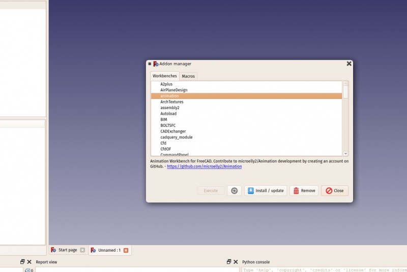
The FreeCAD addons manager
If you are using the Ubuntu operating system, some of the addons above are also available as packages on the FreeCAD addons PPA
Read more
More download options
FreeCAD PPA for Ubuntu
FreeCAD addons PPA for Ubuntu
Compile FreeCAD yourself
FreeCAD translations
FreeCAD github page
The FreeCAD addons manager
 The start center is a convenient "welcome screen", that shows useful information for newcomers, like the latest files you have been working on, what's new in the FreeCAD world, or quick info about the most common Workbenches.
It will also notify you if a new stable version of FreeCAD is available.
After a while, when you are more familiar with FreeCAD, you may have made changes in the preferences so when FreeCAD starts you find yourself directly in one of the Workbenches with a new document open.
Or, simply close the start page tab and create a new document:
The start center is a convenient "welcome screen", that shows useful information for newcomers, like the latest files you have been working on, what's new in the FreeCAD world, or quick info about the most common Workbenches.
It will also notify you if a new stable version of FreeCAD is available.
After a while, when you are more familiar with FreeCAD, you may have made changes in the preferences so when FreeCAD starts you find yourself directly in one of the Workbenches with a new document open.
Or, simply close the start page tab and create a new document:

 The Workbenches often confuse new users, since it's not always easy to know in which Workbench to look for a specific tool.
But they are quick to learn, and after a short while it will feel natural -- realizing it is a convenient way to organize the multitude of tools FreeCAD has to offer.
Workbenches are also fully customizable (see below).
The same tool may appear in more than one workbench.
The button icon for a particular tool will always be the same no matter which workbench it appears in.
Later in this manual, you will also find a table showing the contents of all Workbenches.
The Workbenches often confuse new users, since it's not always easy to know in which Workbench to look for a specific tool.
But they are quick to learn, and after a short while it will feel natural -- realizing it is a convenient way to organize the multitude of tools FreeCAD has to offer.
Workbenches are also fully customizable (see below).
The same tool may appear in more than one workbench.
The button icon for a particular tool will always be the same no matter which workbench it appears in.
Later in this manual, you will also find a table showing the contents of all Workbenches.
 The 3D view is the main component of the interface; it is where the objects you are working with are drawn and manipulated.
You may have several views of the same document (or same objects), or several documents open at the same time.
Each of these views may be individually undocked from the main window.
You may select objects or parts of objects by clicking them, and you can pan, zoom and rotate the view with the mouse buttons.
This will be explained further in the next chapter.
In addition to the 3D view panel, the following information panels are available.
They may be made visible or hidden by selecting them from View → Panels .
The name of the panel appears in the upper left corner of the panel when it is displayed:
The combo view has two tabs:
The Model tab shows you the contents and structure of your document above and the properties (or parameters) of the selected object(s) below.
These properties are separated into two categories:
Data (properties which concern the geometry itself)
View (properties that affect how the geometry looks on screen).
The Tasks tab is where FreeCAD will prompt you for values specific to the workbench and tool you are currently using.
For example, entering a 'length' value when the Draft Workbench Line Tool is being used.
It will clear and switch back to the Model tab after the OK (or Cancel) button is pressed.
Double-clicking the related object in the Model tab will usually reopen the corresponding Task tab in order to modify the settings.
The Tasks tab sometimes has puzzling and frustrating side-effects.
If the Task tab is not empty, some FreeCAD operations will not work as expected.
For example, if you have a single object in your model such as a cube, double-clicking on it will open the Tasks tab to allow you to modify the parameters characterizing the cube.
If you have the Selection view open, you will see the cube's internal name listed there.
The entire cube will turn green in the 3D panel, indicating the entire cube is selected.
Clicking on the background will deselect the entire cube and clear the Selection view.
So far, this is normal behavior.
However, if you now click on a face of the cube, instead of that face being selected, nothing will be selected — because the Tasks tab has not been completed.
Even if you have made no modifications to the parameters there, FreeCAD is waiting for the OK (or other) button in the Tasks tab to be clicked.
The report view is normally hidden, but it is a good idea to open it as it will list any information, warnings or errors to help you decipher (or debug) what you may have done wrong.
The Python console is also hidden by default.
This is where you can interact with the contents of the document using the Python language.
Since every action you do on the FreeCAD interface actually executes a piece of Python code, having this open allows you to watch the code unfold in real time — allowing you a wonderful and easy way to learn a little Python on the way, almost without noticing it.
The tree view displays only the object tree shown under the Model tab in the combo view.
It is normally hidden.
The property view displays only the object property information shown at the bottom of the combo view.
It is normally hidden.
The selection view shows the names of any objects which are currently selected.
These are the objects to which a workbench operation will be applied.
It can be used to refine the selection by deselecting some of those objects before a workbench operation is applied.
The selection view can also be used to search for objects by name and then select them.
By default, the selection view is hidden.
While you can often determine the currently selected object(s) by looking at the object tree in the Model tab of the combo view, for complex operations requiring multiple selections and where selection is difficult it is helpful to make this view visible so you can both see the labels and count the selected objects.
The 3D view is the main component of the interface; it is where the objects you are working with are drawn and manipulated.
You may have several views of the same document (or same objects), or several documents open at the same time.
Each of these views may be individually undocked from the main window.
You may select objects or parts of objects by clicking them, and you can pan, zoom and rotate the view with the mouse buttons.
This will be explained further in the next chapter.
In addition to the 3D view panel, the following information panels are available.
They may be made visible or hidden by selecting them from View → Panels .
The name of the panel appears in the upper left corner of the panel when it is displayed:
The combo view has two tabs:
The Model tab shows you the contents and structure of your document above and the properties (or parameters) of the selected object(s) below.
These properties are separated into two categories:
Data (properties which concern the geometry itself)
View (properties that affect how the geometry looks on screen).
The Tasks tab is where FreeCAD will prompt you for values specific to the workbench and tool you are currently using.
For example, entering a 'length' value when the Draft Workbench Line Tool is being used.
It will clear and switch back to the Model tab after the OK (or Cancel) button is pressed.
Double-clicking the related object in the Model tab will usually reopen the corresponding Task tab in order to modify the settings.
The Tasks tab sometimes has puzzling and frustrating side-effects.
If the Task tab is not empty, some FreeCAD operations will not work as expected.
For example, if you have a single object in your model such as a cube, double-clicking on it will open the Tasks tab to allow you to modify the parameters characterizing the cube.
If you have the Selection view open, you will see the cube's internal name listed there.
The entire cube will turn green in the 3D panel, indicating the entire cube is selected.
Clicking on the background will deselect the entire cube and clear the Selection view.
So far, this is normal behavior.
However, if you now click on a face of the cube, instead of that face being selected, nothing will be selected — because the Tasks tab has not been completed.
Even if you have made no modifications to the parameters there, FreeCAD is waiting for the OK (or other) button in the Tasks tab to be clicked.
The report view is normally hidden, but it is a good idea to open it as it will list any information, warnings or errors to help you decipher (or debug) what you may have done wrong.
The Python console is also hidden by default.
This is where you can interact with the contents of the document using the Python language.
Since every action you do on the FreeCAD interface actually executes a piece of Python code, having this open allows you to watch the code unfold in real time — allowing you a wonderful and easy way to learn a little Python on the way, almost without noticing it.
The tree view displays only the object tree shown under the Model tab in the combo view.
It is normally hidden.
The property view displays only the object property information shown at the bottom of the combo view.
It is normally hidden.
The selection view shows the names of any objects which are currently selected.
These are the objects to which a workbench operation will be applied.
It can be used to refine the selection by deselecting some of those objects before a workbench operation is applied.
The selection view can also be used to search for objects by name and then select them.
By default, the selection view is hidden.
While you can often determine the currently selected object(s) by looking at the object tree in the Model tab of the combo view, for complex operations requiring multiple selections and where selection is difficult it is helpful to make this view visible so you can both see the labels and count the selected objects.

 Read more
Getting started with FreeCAD
Customizing the interface
Workbenches
More about Python
Read more
Getting started with FreeCAD
Customizing the interface
Workbenches
More about Python
 The point where the three axes meet is the origin.
It is the point where the value of all coordinates is zero.
For any given axis, moving in one direction will increase the coordinate value and moving in the opposite direction will decrease the coordinate value.
Every point of every object that exists in the 3D space can be located by its (x,y,z) coordinates.
For example, a point with coordinates (2,3,1) will lie at +2 units on the X axis, +3 units on the Y axis, and +1 unit on the Z axis:
The point where the three axes meet is the origin.
It is the point where the value of all coordinates is zero.
For any given axis, moving in one direction will increase the coordinate value and moving in the opposite direction will decrease the coordinate value.
Every point of every object that exists in the 3D space can be located by its (x,y,z) coordinates.
For example, a point with coordinates (2,3,1) will lie at +2 units on the X axis, +3 units on the Y axis, and +1 unit on the Z axis:
 You can look at that scene from any angle, as if you were holding a camera.
That camera can be moved left, right, up and down (pan), rotated around what it is pointing at (rotate) and brought closer to or further from the scene (zoom).
You can look at that scene from any angle, as if you were holding a camera.
That camera can be moved left, right, up and down (pan), rotated around what it is pointing at (rotate) and brought closer to or further from the scene (zoom).
 Each of these modes allocates different mouse buttons, or mouse + keyboard combinations, or mouse gestures, to these four operations.
The following table shows the principal available modes:
Each of these modes allocates different mouse buttons, or mouse + keyboard combinations, or mouse gestures, to these four operations.
The following table shows the principal available modes:


 or
or


 When using the navigation cluster, a control point will turn light blue when the pointer is hovering over a sensitive area.
If the area below the pointer does not change color, clicking on it will have no affect.
As of this writing (v0.18), there are some registration issues which prevent all parts of some control points from being active.
Clicking on a face will switch the view to that face;
clicking on a corner will switch to a view with that corner pointing towards you.
Clicking one of the four triangles will rotate the view 45 degrees in the indicated direction.
Clicking one of the two curved arrows at the top will rotate the view 45 degrees in the indicated direction around a line pointing towards you.
The navigation cluster may be moved to any part of the 3D display by dragging.
The drag (left) mouse button must be pressed inside the cube itself to initiate a drag.
The structure will not begin moving until the pointer is dragged outside the cube.
There is a smaller mini-cube in the lower right of the cluster which activates a drop-down menu allowing you to switch the viewing mode.
When using the navigation cluster, a control point will turn light blue when the pointer is hovering over a sensitive area.
If the area below the pointer does not change color, clicking on it will have no affect.
As of this writing (v0.18), there are some registration issues which prevent all parts of some control points from being active.
Clicking on a face will switch the view to that face;
clicking on a corner will switch to a view with that corner pointing towards you.
Clicking one of the four triangles will rotate the view 45 degrees in the indicated direction.
Clicking one of the two curved arrows at the top will rotate the view 45 degrees in the indicated direction around a line pointing towards you.
The navigation cluster may be moved to any part of the 3D display by dragging.
The drag (left) mouse button must be pressed inside the cube itself to initiate a drag.
The structure will not begin moving until the pointer is dragged outside the cube.
There is a smaller mini-cube in the lower right of the cluster which activates a drop-down menu allowing you to switch the viewing mode.
 You can also use the Selection View to select objects by searching for a particular object.
Read more
The FreeCAD navigation modes
Navigation Cluster
You can also use the Selection View to select objects by searching for a particular object.
Read more
The FreeCAD navigation modes
Navigation Cluster
 The objects inside a FreeCAD document can be of different types.
Each workbench can add its own types of objects, for example the Mesh Workbench adds mesh objects, the Part Workbench adds Part objects, etc.
If there is at least one document open in FreeCAD, there is always one and only one active document.
That's the document that appears in the current 3D view, the document you are currently working on.
If you switch tabs to another document, that one
becomes the active document.
Most operations always work on the active document.
FreeCAD documents are saved with the .FcStd extension, which is a zip-based compound format, similar to LibreOffice.
If something goes very wrong, it is often possible to unzip it and fix the problem or rescue the data.
Read more
The FreeCAD document
File Format FCStd
The objects inside a FreeCAD document can be of different types.
Each workbench can add its own types of objects, for example the Mesh Workbench adds mesh objects, the Part Workbench adds Part objects, etc.
If there is at least one document open in FreeCAD, there is always one and only one active document.
That's the document that appears in the current 3D view, the document you are currently working on.
If you switch tabs to another document, that one
becomes the active document.
Most operations always work on the active document.
FreeCAD documents are saved with the .FcStd extension, which is a zip-based compound format, similar to LibreOffice.
If something goes very wrong, it is often possible to unzip it and fix the problem or rescue the data.
Read more
The FreeCAD document
File Format FCStd
 Two important things are necessary to know:
Recomputation is not always automatic.
Heavy operations, that might modify a big portion of your document, and therefore take some time, are not performed automatically.
Instead, the object (and all the objects that depend on it) will be marked for recomputation (a small blue icon appears on them in the tree view).
You must then press the recompute button (or Edit->Refresh) to have all the marked objects recomputed.
The dependency tree must always flow in the same direction.
Loops are forbidden.
(See DAG, and DAG view) You can have object A which depends on object B which depend on object C.
But you cannot have object A which depends on object B which depends on object A.
That would be a circular dependency.
However, you can have many objects that depend on the same object, for example objects B and C both depend on A.
Menu Tools -> Dependency graph shows you a dependency diagram like on the image above.
It can be useful to detect problems.
Not all objects are parametric in FreeCAD.
Often, the geometry that you import from other files won't contain any parameter, and will be simple, non-parametric objects.
However, these can often be used as a base, or starting point for newly created parametric objects, depending, of course, on what the parametric object requires and the quality of the imported geometry.
All objects, however, parametric or not, will have a couple of basic parameters, such as a Name, which is unique in the document and cannot be edited, a Label, which is a user-defined name that can be edited, and a placement, which holds its position in the 3D space.
Finally, it is worth noting that custom parametric objects are easy to program in python.
Read more
The properties editor
How to program parametric objects
Positioning objects in FreeCAD
Enabling the dependency graph
Two important things are necessary to know:
Recomputation is not always automatic.
Heavy operations, that might modify a big portion of your document, and therefore take some time, are not performed automatically.
Instead, the object (and all the objects that depend on it) will be marked for recomputation (a small blue icon appears on them in the tree view).
You must then press the recompute button (or Edit->Refresh) to have all the marked objects recomputed.
The dependency tree must always flow in the same direction.
Loops are forbidden.
(See DAG, and DAG view) You can have object A which depends on object B which depend on object C.
But you cannot have object A which depends on object B which depends on object A.
That would be a circular dependency.
However, you can have many objects that depend on the same object, for example objects B and C both depend on A.
Menu Tools -> Dependency graph shows you a dependency diagram like on the image above.
It can be useful to detect problems.
Not all objects are parametric in FreeCAD.
Often, the geometry that you import from other files won't contain any parameter, and will be simple, non-parametric objects.
However, these can often be used as a base, or starting point for newly created parametric objects, depending, of course, on what the parametric object requires and the quality of the imported geometry.
All objects, however, parametric or not, will have a couple of basic parameters, such as a Name, which is unique in the document and cannot be edited, a Label, which is a user-defined name that can be edited, and a placement, which holds its position in the 3D space.
Finally, it is worth noting that custom parametric objects are easy to program in python.
Read more
The properties editor
How to program parametric objects
Positioning objects in FreeCAD
Enabling the dependency graph
 Read more
All file formats supported by FreeCAD
Working with DXF files in FreeCAD:
Enabling DXF and DWG support
Working with SVG files in FreeCAD
Importing and exporting to IFC
OpenCasCade
Teigha File Converter
IFC Specifications Database
IfcOpenShell
Read more
All file formats supported by FreeCAD
Working with DXF files in FreeCAD:
Enabling DXF and DWG support
Working with SVG files in FreeCAD
Importing and exporting to IFC
OpenCasCade
Teigha File Converter
IFC Specifications Database
IfcOpenShell
 Arc 3 points
 Circle 3 points
 Ellipse 3 points
 Arc of ellipse
 Parallel
 Perpendicular
 Tangent
 Equal length
 Symmetric
 Distance
 Radius
 Internal angle
 Snell's law
 Internal alignment
 Scaled
 Involute gear wizard
 New sheet
 View
View Annotation
 Clip
Clip Open browser
 Ortho views
 Symbol
 Draft view
 Save
Save The difference between the two can be compared to the difference between bitmap and vector images.
As with bitmap images, polygon meshes have their curved surfaces divided into a series of points.
If you look at it closely, or print it very large, you will see not a curved but a faceted surface.
In both vector images and BREP data, the position of any point on a curve is not stored in the geometry but calculated on the fly, with exact precision.
In FreeCAD, all BREP-based geometry is handled by another piece of open source software, OpenCasCade.
The main interface between FreeCAD and the OpenCasCade kernel is the Part Workbench.
Most other workbenches build their functionality on top of the Part Workbench.
Although other workbenches often offer more advanced tools to build and manipulate geometry, since they all actually manipulate Part objects, it is very useful to know how these objects work internally, and be able to use the Part tools since, being more simple, they can very often help you to work around problems that the more intelligent tools fail to solve properly.
To illustrate the working of the Part Workbench, we will model this table, using only CSG operations (except the screws, for which we will use one of the addons, and the dimensions, which will see in the next chapter):
The difference between the two can be compared to the difference between bitmap and vector images.
As with bitmap images, polygon meshes have their curved surfaces divided into a series of points.
If you look at it closely, or print it very large, you will see not a curved but a faceted surface.
In both vector images and BREP data, the position of any point on a curve is not stored in the geometry but calculated on the fly, with exact precision.
In FreeCAD, all BREP-based geometry is handled by another piece of open source software, OpenCasCade.
The main interface between FreeCAD and the OpenCasCade kernel is the Part Workbench.
Most other workbenches build their functionality on top of the Part Workbench.
Although other workbenches often offer more advanced tools to build and manipulate geometry, since they all actually manipulate Part objects, it is very useful to know how these objects work internally, and be able to use the Part tools since, being more simple, they can very often help you to work around problems that the more intelligent tools fail to solve properly.
To illustrate the working of the Part Workbench, we will model this table, using only CSG operations (except the screws, for which we will use one of the addons, and the dimensions, which will see in the next chapter):
 Let's create a new document (Ctrl+N or menu File → New Document) to hold our table design.
The document is initially called "unnamed" in the Model tab in the Combo View panel, but if you save the document (Ctrl+Shift+S or menu File → Save As) as a new FreeCAD document called "table.FCStd" the document will be renamed "table", which more clearly identifies the project.
Now we can switch to the Part Workbench and start to create our first table leg.
Press the
Let's create a new document (Ctrl+N or menu File → New Document) to hold our table design.
The document is initially called "unnamed" in the Model tab in the Combo View panel, but if you save the document (Ctrl+Shift+S or menu File → Save As) as a new FreeCAD document called "table.FCStd" the document will be renamed "table", which more clearly identifies the project.
Now we can switch to the Part Workbench and start to create our first table leg.
Press the
 Now we can subtract one from the other: Select the first one, that is, the one that will stay, then, with the CTRL key pressed, select the other one, that will be subtracted (the order is important) and press the
 Observe that the newly created object, called "Cut", still contains the two cubes we used as operands.
In fact, the two cubes are still there in the document, they have merely been hidden and grouped under the Cut object in the tree view.
You can still select them by expanding the arrow next to the Cut object, and, if you wish, turn them visible again by right-clicking them or change any of their properties.
You can use Cut -tool and other Boolean tools also through "Combo view" with
Observe that the newly created object, called "Cut", still contains the two cubes we used as operands.
In fact, the two cubes are still there in the document, they have merely been hidden and grouped under the Cut object in the tree view.
You can still select them by expanding the arrow next to the Cut object, and, if you wish, turn them visible again by right-clicking them or change any of their properties.
You can use Cut -tool and other Boolean tools also through "Combo view" with
 You might have been thinking that, instead of duplicating the base cube six times, we could have duplicated the complete foot three times.
This is totally true, as always in FreeCAD, there are many ways to achieve a same result.
This is a precious thing to remember, because, as we will advance into more complex objects, some operations might not give the correct result and we often need to try other ways.
We will now make holes for the screws, using the same Cut method.
Since we need 8 holes, two in each foot, we could make 8 objects to be subtracted.
Instead, let's explore other ways and make 4 tubes, that will be reused by two of the feet.
So let's create four tubes by using the
You might have been thinking that, instead of duplicating the base cube six times, we could have duplicated the complete foot three times.
This is totally true, as always in FreeCAD, there are many ways to achieve a same result.
This is a precious thing to remember, because, as we will advance into more complex objects, some operations might not give the correct result and we often need to try other ways.
We will now make holes for the screws, using the same Cut method.
Since we need 8 holes, two in each foot, we could make 8 objects to be subtracted.
Instead, let's explore other ways and make 4 tubes, that will be reused by two of the feet.
So let's create four tubes by using the
 You will notice that the cylinders are a bit longer than needed.
This is because, as in all solid-based 3D applications, boolean operations in FreeCAD are sometimes oversensitive to face-on-face situations and might fail.
By doing this, we put ourselves on the safe side.
Now let's do the subtractions.
Select the first foot, then, with CTRL pressed, select one of the tubes that crosses it, press the Cut button.
The hole will be done, and the tube hidden.
Find it in the tree view by expanding the pierced foot.
Select another foot pierced by this hidden tube, then repeat the operation, this time Ctrl+ selecting the tube in the tree view, as it is hidden in the 3D view (you can also make it visible again and select it in the 3D view).
Repeat this for the other feet until each of them has its two holes:
You will notice that the cylinders are a bit longer than needed.
This is because, as in all solid-based 3D applications, boolean operations in FreeCAD are sometimes oversensitive to face-on-face situations and might fail.
By doing this, we put ourselves on the safe side.
Now let's do the subtractions.
Select the first foot, then, with CTRL pressed, select one of the tubes that crosses it, press the Cut button.
The hole will be done, and the tube hidden.
Find it in the tree view by expanding the pierced foot.
Select another foot pierced by this hidden tube, then repeat the operation, this time Ctrl+ selecting the tube in the tree view, as it is hidden in the 3D view (you can also make it visible again and select it in the 3D view).
Repeat this for the other feet until each of them has its two holes:
 As you can see, each foot has become a quite long series of operations.
All this stays parametric, and you can go change any parameter of any of the older operations anytime.
In FreeCAD, we often refer to this pile as "modeling history", since it in fact carries all the history of the operations you did.
Another particularity of FreeCAD is that the concept of 3D object and the concept of 3D operation tend to blend into one same thing.
The Cut is at the same time an operation, and the 3D object resulting from this operation.
In FreeCAD this is called a "feature", rather than object or operation.
Now let's do the tabletop, it will be a simple block of wood, let's do it with another Box with length: 126cm, width: 86cm, height: 8cm, position: x: 10mm, y: 10mm, z, 67cm.
In the View tab, you can give it a nice brownish, wood-like color by changing its Shape Color property:
As you can see, each foot has become a quite long series of operations.
All this stays parametric, and you can go change any parameter of any of the older operations anytime.
In FreeCAD, we often refer to this pile as "modeling history", since it in fact carries all the history of the operations you did.
Another particularity of FreeCAD is that the concept of 3D object and the concept of 3D operation tend to blend into one same thing.
The Cut is at the same time an operation, and the 3D object resulting from this operation.
In FreeCAD this is called a "feature", rather than object or operation.
Now let's do the tabletop, it will be a simple block of wood, let's do it with another Box with length: 126cm, width: 86cm, height: 8cm, position: x: 10mm, y: 10mm, z, 67cm.
In the View tab, you can give it a nice brownish, wood-like color by changing its Shape Color property:
 Notice that, although the legs are 8mm thick, we placed it 10mm away, leaving 2mm between them.
This is not necessary, of course, it won't happen with the real table, but it is a common thing to do in that kind of "assembled" models, it helps people who look at the model to understand that these are independent parts, that will need to be attached together manually later.
Now that our five pieces are complete, it is a good time to give them more proper names than "Cut015".
By right-clicking the objects in the tree view (or pressing F2), you can rename them to something more meaningful to yourself or to another person who would open your file later.
It is often said that simply giving proper names to your objects is much more important than the way you model them.
We will now place some screws.
There is nowadays an extremely useful addon developed by a member of the FreeCAD community, that you can find on the FreeCAD addons repository, called Fasteners, that makes the insertion of screws very easy.
Installing additional workbenches is easy and described on the addons pages.
Once you have installed the Fasteners Workbench and restarted FreeCAD, it will appear in the workbenches list, and we can switch to it.
Adding a screw to one of our holes is done by first selecting the circular edge of our hole:
Notice that, although the legs are 8mm thick, we placed it 10mm away, leaving 2mm between them.
This is not necessary, of course, it won't happen with the real table, but it is a common thing to do in that kind of "assembled" models, it helps people who look at the model to understand that these are independent parts, that will need to be attached together manually later.
Now that our five pieces are complete, it is a good time to give them more proper names than "Cut015".
By right-clicking the objects in the tree view (or pressing F2), you can rename them to something more meaningful to yourself or to another person who would open your file later.
It is often said that simply giving proper names to your objects is much more important than the way you model them.
We will now place some screws.
There is nowadays an extremely useful addon developed by a member of the FreeCAD community, that you can find on the FreeCAD addons repository, called Fasteners, that makes the insertion of screws very easy.
Installing additional workbenches is easy and described on the addons pages.
Once you have installed the Fasteners Workbench and restarted FreeCAD, it will appear in the workbenches list, and we can switch to it.
Adding a screw to one of our holes is done by first selecting the circular edge of our hole:
 Then we can press one of the screw buttons of the Fasteners Workbench, for example the EN 1665 Hexagon bolt with flanges, heavy series.
The screw will be placed and aligned with our hole, and the diameter will automatically be selected to match the size of our hole.
Sometimes the screw will be placed inverted, which we can correct by flipping its invert property.
We can also set its offset to 2mm, to follow the same rule we used between the tabletop and the feet:
Then we can press one of the screw buttons of the Fasteners Workbench, for example the EN 1665 Hexagon bolt with flanges, heavy series.
The screw will be placed and aligned with our hole, and the diameter will automatically be selected to match the size of our hole.
Sometimes the screw will be placed inverted, which we can correct by flipping its invert property.
We can also set its offset to 2mm, to follow the same rule we used between the tabletop and the feet:
 Repeat this for all the holes, and our table is complete!
The internal structure of Part objects
As we saw above, it is possible in FreeCAD to select not only whole objects, but parts of them, such as the circular border of our screw hole.
This is a good time to have a quick look at how Part objects are constructed internally.
Every workbench that produces Part geometry will be based on these:
Vertices: These are points (usually endpoints) on which all the rest is built.
For example, a line has two vertices.
Edges: the edges are linear geometry like lines, arcs, ellipses or NURBS curves.
They usually have two vertices, but some special cases have only one (a closed circle for example).
Wires: A wire is a sequence of edges connected by their endpoints.
It can contain edges of any type, and it can be closed or not.
Faces: Faces can be planar or curved, and can be formed by one closed wire, which forms the border of the face, or more than one, in case the face has holes.
Shells: Shells are simply a group of faces connected by their edges.
It can be open or closed.
Solids: When a shell is tightly closed, that is, it has no "leak", it becomes a solid.
Solids carry the notion of inside and outside.
Many workbenches rely on this to make sure the objects they produce can be built in the real world.
Compounds: Compounds are simply aggregates of other shapes, no matter their type, into a single shape.
In the 3D view, you can select individual vertices, edges or faces.
Selecting one of these also selects the whole object.
A note about shared design
You might look at the table above, and think its design is not good.
The tightening of the feet with the tabletop is probably too weak.
You might want to add reinforcing pieces, or simply you have other ideas to make it better.
This is where sharing becomes interesting.
You can download the file made during this exercise from the link below, and modify it to make it better.
Then, if you share that improved file, others might be able to make it even better, or use your well-designed table in their projects.
Your design might then give other ideas to other people, and maybe you will have helped a tiny bit to make a better world...
Downloads
The file produced in this exercise: https://github.com/yorikvanhavre/FreeCAD-manual/blob/master/files/table.FCStd
Read more
The Part Workbench
The FreeCAD addons repository
The Fasteners Workbench
Repeat this for all the holes, and our table is complete!
The internal structure of Part objects
As we saw above, it is possible in FreeCAD to select not only whole objects, but parts of them, such as the circular border of our screw hole.
This is a good time to have a quick look at how Part objects are constructed internally.
Every workbench that produces Part geometry will be based on these:
Vertices: These are points (usually endpoints) on which all the rest is built.
For example, a line has two vertices.
Edges: the edges are linear geometry like lines, arcs, ellipses or NURBS curves.
They usually have two vertices, but some special cases have only one (a closed circle for example).
Wires: A wire is a sequence of edges connected by their endpoints.
It can contain edges of any type, and it can be closed or not.
Faces: Faces can be planar or curved, and can be formed by one closed wire, which forms the border of the face, or more than one, in case the face has holes.
Shells: Shells are simply a group of faces connected by their edges.
It can be open or closed.
Solids: When a shell is tightly closed, that is, it has no "leak", it becomes a solid.
Solids carry the notion of inside and outside.
Many workbenches rely on this to make sure the objects they produce can be built in the real world.
Compounds: Compounds are simply aggregates of other shapes, no matter their type, into a single shape.
In the 3D view, you can select individual vertices, edges or faces.
Selecting one of these also selects the whole object.
A note about shared design
You might look at the table above, and think its design is not good.
The tightening of the feet with the tabletop is probably too weak.
You might want to add reinforcing pieces, or simply you have other ideas to make it better.
This is where sharing becomes interesting.
You can download the file made during this exercise from the link below, and modify it to make it better.
Then, if you share that improved file, others might be able to make it even better, or use your well-designed table in their projects.
Your design might then give other ideas to other people, and maybe you will have helped a tiny bit to make a better world...
Downloads
The file produced in this exercise: https://github.com/yorikvanhavre/FreeCAD-manual/blob/master/files/table.FCStd
Read more
The Part Workbench
The FreeCAD addons repository
The Fasteners Workbench
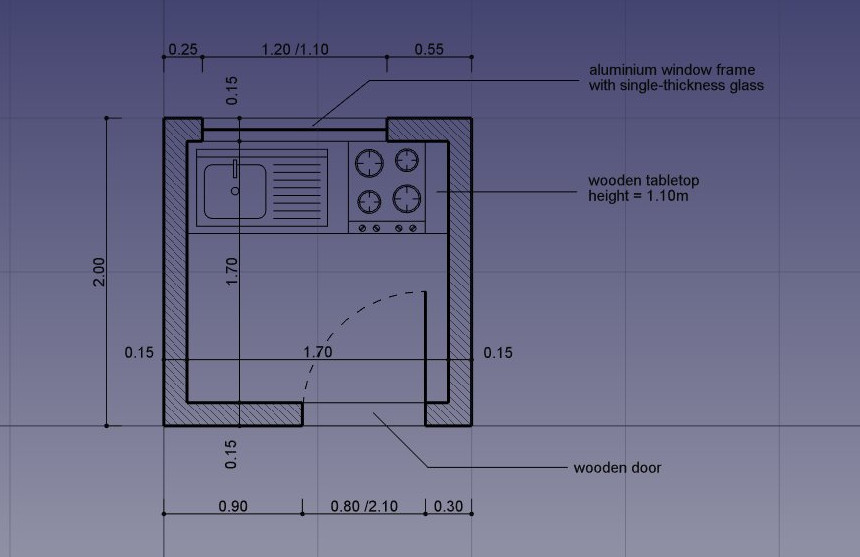 Switch to the Draft Workbench
As in all technical drawing applications, it is wise to set up your environment correctly, it will save you a lot of time.
Configure the grid and working plane, Text and Dimension settings to your liking in menu Edit → Preferences → Draft.
In this exercise, however, we will act as if these settings were left at their default values.
Switch to the Draft Workbench
As in all technical drawing applications, it is wise to set up your environment correctly, it will save you a lot of time.
Configure the grid and working plane, Text and Dimension settings to your liking in menu Edit → Preferences → Draft.
In this exercise, however, we will act as if these settings were left at their default values.
 One option might need your attention, though: the "Fill objects with faces whenever possible" option.
If this is marked, closed objects like rectangles or circles will be filled with a face by default, which can make snapping to underlying objects difficult.
You can either turn this option off now, or, later on, turn the "Make Face" property of each individual object off, to prevent them from creating a face.
The Draft Workbench also has two special toolbars: One with visual settings, where you can change the current working plane, turn construction mode on/off, set the line color, face color, line weight and text size to be used for new objects, and another one with snap locations.
There, you can turn the grid on/off and set/unset individual Snap locations:
One option might need your attention, though: the "Fill objects with faces whenever possible" option.
If this is marked, closed objects like rectangles or circles will be filled with a face by default, which can make snapping to underlying objects difficult.
You can either turn this option off now, or, later on, turn the "Make Face" property of each individual object off, to prevent them from creating a face.
The Draft Workbench also has two special toolbars: One with visual settings, where you can change the current working plane, turn construction mode on/off, set the line color, face color, line weight and text size to be used for new objects, and another one with snap locations.
There, you can turn the grid on/off and set/unset individual Snap locations:
 Turning on all the snap buttons is convenient, but also makes drawing slower, as more calculation needs to be done when you move the mouse cursor.
It is often better to keep only the ones you will actually use.
Let's start by turning construction mode on, which will allow us to draw some guidelines on which we will draw our final geometry.
If you wish, set the working plane to XY.
If you do this, the working plane won't change, no matter the current view.
If not, the working plane will adapt automatically to the current view, and you should take care of staying in top view whenever you want to draw on the XY (ground) plane.
Then, select the
Turning on all the snap buttons is convenient, but also makes drawing slower, as more calculation needs to be done when you move the mouse cursor.
It is often better to keep only the ones you will actually use.
Let's start by turning construction mode on, which will allow us to draw some guidelines on which we will draw our final geometry.
If you wish, set the working plane to XY.
If you do this, the working plane won't change, no matter the current view.
If not, the working plane will adapt automatically to the current view, and you should take care of staying in top view whenever you want to draw on the XY (ground) plane.
Then, select the
 We can then draw a couple of vertical lines to define where our doors and windows will be placed, using the
 That is all we need now, so we can switch construction mode off.
Check that all the construction geometry has been placed into a "Construction" group, which makes it easy to hide it all at once or even delete it completely later on.
Now let's draw our two wall pieces using the
That is all we need now, so we can switch construction mode off.
Check that all the construction geometry has been placed into a "Construction" group, which makes it easy to hide it all at once or even delete it completely later on.
Now let's draw our two wall pieces using the
 We can change their default grey color to a nice hatch pattern, by selecting both walls, then setting their Pattern property to Simple, and their Pattern size to your liking, for example 0.005.
 We can now hide the construction geometry by right-clicking the Construction group and choose Hide Selection.
Let's now draw the windows and doors.
Make sure the
We can now hide the construction geometry by right-clicking the Construction group and choose Hide Selection.
Let's now draw the windows and doors.
Make sure the
 We will now change the door line to create an opened door symbol.
Start by rotating the line using the
We will now change the door line to create an opened door symbol.
Start by rotating the line using the
 We can now start placing some furniture.
To begin with, let's place a counter by drawing a rectangle from the upper left inner corner, and giving it a width of 170cm and a height of -60cm.
In the image below, the Transparency property of the rectangle is set to 80%, to give it a nice furniture look.
Then let's add a sink and a cookertop.
Drawing these kinds of symbols by hand can be very tedious, and they are usually easy to find on the internet, for example on http://www.cad-blocks.net .
In the Downloads section below, for convenience, we separated a sink and a cookertop from this project, and saved them as DXF files.You can download these two files by visiting the links below, and right-clicking the Raw button, then choosing save as.
Inserting a DXF file into an opened FreeCAD document can be done either by choosing the File → Import menu option, or by dragging and dropping the DXF file from your file explorer into the FreeCAD window.
The contents of the DXF files might not appear right on the center of your current view, depending on where they were in the DXF file.
You can use menu View → Standard views → Fit all to zoom out and find the imported objects.
Insert the two DXF files, and move them to a suitable location on the tabletop:
We can now start placing some furniture.
To begin with, let's place a counter by drawing a rectangle from the upper left inner corner, and giving it a width of 170cm and a height of -60cm.
In the image below, the Transparency property of the rectangle is set to 80%, to give it a nice furniture look.
Then let's add a sink and a cookertop.
Drawing these kinds of symbols by hand can be very tedious, and they are usually easy to find on the internet, for example on http://www.cad-blocks.net .
In the Downloads section below, for convenience, we separated a sink and a cookertop from this project, and saved them as DXF files.You can download these two files by visiting the links below, and right-clicking the Raw button, then choosing save as.
Inserting a DXF file into an opened FreeCAD document can be done either by choosing the File → Import menu option, or by dragging and dropping the DXF file from your file explorer into the FreeCAD window.
The contents of the DXF files might not appear right on the center of your current view, depending on where they were in the DXF file.
You can use menu View → Standard views → Fit all to zoom out and find the imported objects.
Insert the two DXF files, and move them to a suitable location on the tabletop:
 We can now place a couple of dimensions using the
 Let's add some description texts using the
 Our drawing is now complete! Since there are quite a number of objects there, it would be wise do some cleaning and restructure everything into nice groups, to make the file easier to understand for other people:
 We can now print our work by placing it on a Drawing sheet, which we will show later in this manual, or directly export our drawing to other CAD applications, by exporting it to a DXF file.
Simply select our "Floor plan" group, select menu File → Export, and select the Autodesk DXF format.
The file can then be opened in any other 2D CAD application such as LibreCAD.
You might notice some differences, depending on the configurations of each application.
We can now print our work by placing it on a Drawing sheet, which we will show later in this manual, or directly export our drawing to other CAD applications, by exporting it to a DXF file.
Simply select our "Floor plan" group, select menu File → Export, and select the Autodesk DXF format.
The file can then be opened in any other 2D CAD application such as LibreCAD.
You might notice some differences, depending on the configurations of each application.
 The most important thing about the Draft Workbench, however, is that the geometry you create with it can be used as a base or easily extruded into 3D objects, simply by using the
 All kinds of openings can also be done as easily by drawing Draft objects on the faces of walls, then extruding them, then using the boolean tools from the Part Workbench to subtract them from another solid, as we saw in the previous chapter.
Fundamentally, what the Draft Workbench does is to provide graphical ways to create basic Part operations.
While in Part you will usually position objects by setting their placement parameter, in Draft you can do it on-screen.
There are times when one is better, other times when the other is preferable.
Don't forget, you can create custom toolbars in one of these workbenches, add the tools from the other, and get the best of both worlds.
All kinds of openings can also be done as easily by drawing Draft objects on the faces of walls, then extruding them, then using the boolean tools from the Part Workbench to subtract them from another solid, as we saw in the previous chapter.
Fundamentally, what the Draft Workbench does is to provide graphical ways to create basic Part operations.
While in Part you will usually position objects by setting their placement parameter, in Draft you can do it on-screen.
There are times when one is better, other times when the other is preferable.
Don't forget, you can create custom toolbars in one of these workbenches, add the tools from the other, and get the best of both worlds.
 Select the Standard mesher, and leave the deviation value to the default value of 0.10.
Press Ok.
A mesh object will be created, exactly on top of our solid object.
Either hide the solid, or move one of the objects aside, so you can compare both.
Change the View → Display Mode property of the new mesh object to Flat Lines, in order to see how the triangulation occurred.
If you are not happy, and think that the result is too coarse, you can repeat the operation, lowering the deviation value.
In the example below, the left mesh used the default value of 0.10, while the right one uses 0.01:
Select the Standard mesher, and leave the deviation value to the default value of 0.10.
Press Ok.
A mesh object will be created, exactly on top of our solid object.
Either hide the solid, or move one of the objects aside, so you can compare both.
Change the View → Display Mode property of the new mesh object to Flat Lines, in order to see how the triangulation occurred.
If you are not happy, and think that the result is too coarse, you can repeat the operation, lowering the deviation value.
In the example below, the left mesh used the default value of 0.10, while the right one uses 0.01:
 In most cases, though, the default values will give a satisfying result.
We can now export our mesh to a mesh format, such as STL, which is currently the most widely used format in 3D printing, by using menu File → Export and choosing the STL file format.
If you don't own a 3D printer, it is usually very easy to find commercial services that will print and send you the printed objects by mail.
Among the famous ones are Shapeways and Sculpteo, but you will usually find many others in your own city.
In all major cities, you will nowadays find Fab labs, which are workshops equipped with a range of 3D manufacturing machines, almost always including at least one 3D printer.
Fab labs are usually community spaces, that will let you use their machines, for a fee or for free depending on the Fab lab, but also teach you how to use them, and promote other activities around 3D manufacturing.
In most cases, though, the default values will give a satisfying result.
We can now export our mesh to a mesh format, such as STL, which is currently the most widely used format in 3D printing, by using menu File → Export and choosing the STL file format.
If you don't own a 3D printer, it is usually very easy to find commercial services that will print and send you the printed objects by mail.
Among the famous ones are Shapeways and Sculpteo, but you will usually find many others in your own city.
In all major cities, you will nowadays find Fab labs, which are workshops equipped with a range of 3D manufacturing machines, almost always including at least one 3D printer.
Fab labs are usually community spaces, that will let you use their machines, for a fee or for free depending on the Fab lab, but also teach you how to use them, and promote other activities around 3D manufacturing.

 The generated G-code can also be re-imported into FreeCAD (using the slic3r preprocessor) for checking.
 Then, let's duplicate this first loop a couple of times, so the tool will carve out the whole block.
Select the Profile path, and press the
Then, let's duplicate this first loop a couple of times, so the tool will carve out the whole block.
Select the Profile path, and press the
 Now we have defined a path that, when followed by the milling machine, will carve a rectangular volume out of a block of material.
We now need to carve out the space between the dots, in order to reveal them.
Hide the Pad, and show the final piece again, so we can select the face that lies between the dots.
Select the top face, and press the
Now we have defined a path that, when followed by the milling machine, will carve a rectangular volume out of a block of material.
We now need to carve out the space between the dots, in order to reveal them.
Hide the Pad, and show the final piece again, so we can select the face that lies between the dots.
Select the top face, and press the
 Once again, make an array.
Select the Pocket object, and press the
Once again, make an array.
Select the Pocket object, and press the
 Now all that is left to do is to join these two operations into one.
This can be done with a Path Job.
Press the
Now all that is left to do is to join these two operations into one.
This can be done with a Path Job.
Press the
 Load the IkeaLikeChair file from the library.
You can choose between the .FCStd version, which will load the full modeling history, or the .step version, which will create only one object, without the history.
Since we won't need to model any further now, it is best to choose the .step version, as it will be easier to manipulate.
Load the IkeaLikeChair file from the library.
You can choose between the .FCStd version, which will load the full modeling history, or the .step version, which will create only one object, without the history.
Since we won't need to model any further now, it is best to choose the .step version, as it will be easier to manipulate.
 Switch to the
 Let's repeat the operation twice, to create two more views.
We will set their X and Y values, which indicate the position of the view on the page, in order to show them apart from the top view, and their direction, to create different view orientations.
Give each new view the following properties:
View001 (front view): X: 70, Y: 220, Scale: 0.1, Rotation: 0, Direction: (-1,0,0), XDirection: (0,-1,0)
View002 (side view): X: 150, Y: 220, Scale: 0.1, Rotation: 0, Direction: (0,-1,0), XDirection: (1,0,0)
After that, we obtain the following page:
Let's repeat the operation twice, to create two more views.
We will set their X and Y values, which indicate the position of the view on the page, in order to show them apart from the top view, and their direction, to create different view orientations.
Give each new view the following properties:
View001 (front view): X: 70, Y: 220, Scale: 0.1, Rotation: 0, Direction: (-1,0,0), XDirection: (0,-1,0)
View002 (side view): X: 150, Y: 220, Scale: 0.1, Rotation: 0, Direction: (0,-1,0), XDirection: (1,0,0)
After that, we obtain the following page:
 Note that there may be easier ways to get the views that you want.
You can simply rotate the 3D view of your model, and once you have the view you want, select the model in the tree view and hit
Note that there may be easier ways to get the views that you want.
You can simply rotate the 3D view of your model, and once you have the view you want, select the model in the tree view and hit
 Repeat the operation, until all the dimensions you wish to indicate are placed.
Use the
Repeat the operation, until all the dimensions you wish to indicate are placed.
Use the
 We will now place the two callouts shown in the image above, using the
 Looking at the Page in the 3D view window, select the View to which the Balloon will be attached, as shown in the image above.
Press the
Looking at the Page in the 3D view window, select the View to which the Balloon will be attached, as shown in the image above.
Press the
 and produce a plan and a section view from it:
 Create a new document, and switch to the Arch Workbench.
Open menu Edit → Preferences → Draft → Grid and Snapping and set:
Main lines every
Create a new document, and switch to the Arch Workbench.
Open menu Edit → Preferences → Draft → Grid and Snapping and set:
Main lines every  Notice that we drew always in the same direction (clockwise).
This is not necessary, but will ensure that the walls that we will build next all have the same left and right directions.
You might also think we could simply have drawn a rectangle here, which is true.
But the four lines will allow us to illustrate better how to add one object into another.
Once your have created the lines check their start and end points and adjust if necessary to get them exactly correct.
Notice that we drew always in the same direction (clockwise).
This is not necessary, but will ensure that the walls that we will build next all have the same left and right directions.
You might also think we could simply have drawn a rectangle here, which is true.
But the four lines will allow us to illustrate better how to add one object into another.
Once your have created the lines check their start and end points and adjust if necessary to get them exactly correct.
 Select the first line, then press the
 Now we need to join these walls together, so they intersect properly.
This is not necessary when your walls are drawn in a way that they already connect cleanly, but here we need to, since they are intersecting.
In Arch, this is done by electing one of the walls to be the "host", and adding the others to it, as "additions".
All arch objects can have any number of additions (objects whose geometry will be added to the host's geometry), and subtractions (objects whose geometry will be subtracted).
The additions and subtractions of an object can be managed anytime by double-clicking the object in the tree.
Select the four walls with Ctrl pressed, the last one being the wall that you chose to become the host
Press the
Now we need to join these walls together, so they intersect properly.
This is not necessary when your walls are drawn in a way that they already connect cleanly, but here we need to, since they are intersecting.
In Arch, this is done by electing one of the walls to be the "host", and adding the others to it, as "additions".
All arch objects can have any number of additions (objects whose geometry will be added to the host's geometry), and subtractions (objects whose geometry will be subtracted).
The additions and subtractions of an object can be managed anytime by double-clicking the object in the tree.
Select the four walls with Ctrl pressed, the last one being the wall that you chose to become the host
Press the
 The individual walls are however still accessible, by expanding the wall in the tree view.
Let's now place a door.
In FreeCAD, doors are considered a special case of windows, so this is done using the Window tool.
Start by selecting the wall.
This is not necessary, but a good habit to take.
If an object is selected when starting the window tool, you will force the window to be inserted in that object, even if you snap to another object.
Set the Working Plane to auto so we are not restricted to the ground plane
Press the
The individual walls are however still accessible, by expanding the wall in the tree view.
Let's now place a door.
In FreeCAD, doors are considered a special case of windows, so this is done using the Window tool.
Start by selecting the wall.
This is not necessary, but a good habit to take.
If an object is selected when starting the window tool, you will force the window to be inserted in that object, even if you snap to another object.
Set the Working Plane to auto so we are not restricted to the ground plane
Press the
 After clicking, our window is placed on the correct face, but not exactly where we want:
 We can now set the precise location by expanding the wall and the window objects in the tree view, and changing the Placement property of the base sketch of our door.
Set its position to x = 2m, y = 0, z = 0.
Our window is now exactly where we want it:
We can now set the precise location by expanding the wall and the window objects in the tree view, and changing the Placement property of the base sketch of our door.
Set its position to x = 2m, y = 0, z = 0.
Our window is now exactly where we want it:
 Repeat the operation to place a window: Select the wall, press the window tool, select the Open 2-pane preset, and place a 1m x 1m window in the same face as the door.
Set the placement of the underlying sketch to position x = 0.6m, y = 0, z = 1.1m, so the upper line of the window is aligned to the top of the door.
Repeat the operation to place a window: Select the wall, press the window tool, select the Open 2-pane preset, and place a 1m x 1m window in the same face as the door.
Set the placement of the underlying sketch to position x = 0.6m, y = 0, z = 1.1m, so the upper line of the window is aligned to the top of the door.
 Windows are always built on sketches.
It is easy to create custom windows by first creating a sketch on a face, then turning it into a window by selecting it, then pressing the window button.
Then, the window creation parameters, that is, which wires of the sketch must be extruded and how much, can be defined by double-clicking the window in the tree view.
Now, let's create a slab:
Set the Working Plane to XY plane
Create a
Windows are always built on sketches.
It is easy to create custom windows by first creating a sketch on a face, then turning it into a window by selecting it, then pressing the window button.
Then, the window creation parameters, that is, which wires of the sketch must be extruded and how much, can be defined by double-clicking the window in the tree view.
Now, let's create a slab:
Set the Working Plane to XY plane
Create a
 Let's now use one of the structural presets to make a metallic beam.
Click the
Let's now use one of the structural presets to make a metallic beam.
Click the
 Adjust its placement by setting its Angle to 90° in the (1,0,0) axis, and its position to x:90mm, y:3.5m, z:3.09m.
This will position the beam exactly on one of the side walls:
Adjust its placement by setting its Angle to 90° in the (1,0,0) axis, and its position to x:90mm, y:3.5m, z:3.09m.
This will position the beam exactly on one of the side walls:
 We need now to duplicate this beam a couple of times.
We could do that one by one using the
We need now to duplicate this beam a couple of times.
We could do that one by one using the
 expression icon at the right side of the X field.
This will open an expressions editor:
expression icon at the right side of the X field.
This will open an expressions editor:
 Write (4m-180mm)/5 in the expression field, and press OK.
This will set the x value to 0.764 (4m is the total length of our front wall, 180mm is the width of the beam, which is why it is called HEB180, and we want a fifth of that space as interval between each beam):
Write (4m-180mm)/5 in the expression field, and press OK.
This will set the x value to 0.764 (4m is the total length of our front wall, 180mm is the width of the beam, which is why it is called HEB180, and we want a fifth of that space as interval between each beam):
 We can now easily build a simple slab on top of them, by drawing a rectangle directly on the top plane of the beams.
Select a top face of one of the beams
Press the
We can now easily build a simple slab on top of them, by drawing a rectangle directly on the top plane of the beams.
Select a top face of one of the beams
Press the
 Select the rectangle
Click the
Select the rectangle
Click the
 The IFC format is one of the most precious assets in a free BIM world, because it allows the exchange of data between any application and actor of the construction world, in an open manner (the format is open, free and maintained by an independent consortium).
Exporting your BIM models as IFC ensures that anyone can see and analyze them, no matter the application used.
In FreeCAD, IFC import and export is done by interfacing with another piece of software, called IfcOpenShell.
To be able to export to IFC from FreeCAD, the IfcOpenShell-python package must be installed on your system.
Be sure to select one which uses the same python version as FreeCAD.
The python version that FreeCAD uses is informed when opening the View -> Panels -> Python console panel in FreeCAD.
When that is done, we can now export our model:
Select the top object you want to export, that is, the Building object.
Select menu File -> Export -> Industry Foundation Classes and save your file.
The resulting IFC file can now be opened in a wide range of applications and viewers (the image below shows the file opened in the free IfcPlusPlus viewer).
Checking the exported file in such a viewer application before distributing it to other people is important to check that all the data contained in the file is correct.
FreeCAD itself can also be used to re-open the resulting IFC file.
The IFC format is one of the most precious assets in a free BIM world, because it allows the exchange of data between any application and actor of the construction world, in an open manner (the format is open, free and maintained by an independent consortium).
Exporting your BIM models as IFC ensures that anyone can see and analyze them, no matter the application used.
In FreeCAD, IFC import and export is done by interfacing with another piece of software, called IfcOpenShell.
To be able to export to IFC from FreeCAD, the IfcOpenShell-python package must be installed on your system.
Be sure to select one which uses the same python version as FreeCAD.
The python version that FreeCAD uses is informed when opening the View -> Panels -> Python console panel in FreeCAD.
When that is done, we can now export our model:
Select the top object you want to export, that is, the Building object.
Select menu File -> Export -> Industry Foundation Classes and save your file.
The resulting IFC file can now be opened in a wide range of applications and viewers (the image below shows the file opened in the free IfcPlusPlus viewer).
Checking the exported file in such a viewer application before distributing it to other people is important to check that all the data contained in the file is correct.
FreeCAD itself can also be used to re-open the resulting IFC file.
 We will now place some dimensions.
Unlike the previous chapter, where we drew all the dimensions directly on the Drawing sheet, we will use another method here, and place Draft dimensions directly in the 3D model.
These dimensions will then be placed on the Drawing sheet automatically.
We will first make two groups for our dimensions, one for the dimensions that will appear in the plan view, and another for those that appear on the elevation.
Right-click the "house" document in the tree view, and create two new groups: Plan dimensions and Elevation dimensions.
Set the Working Plane to XY plane
Make sure the
We will now place some dimensions.
Unlike the previous chapter, where we drew all the dimensions directly on the Drawing sheet, we will use another method here, and place Draft dimensions directly in the 3D model.
These dimensions will then be placed on the Drawing sheet automatically.
We will first make two groups for our dimensions, one for the dimensions that will appear in the plan view, and another for those that appear on the elevation.
Right-click the "house" document in the tree view, and create two new groups: Plan dimensions and Elevation dimensions.
Set the Working Plane to XY plane
Make sure the
 Select all your dimensions, and drag them to the Plan dimensions group in the tree view
Set the Working Plane to XZ plane, that is, the frontal vertical plane.
Repeat the operation, draw a couple of dimensions, and place them in the Elevation dimensions group.
Select all your dimensions, and drag them to the Plan dimensions group in the tree view
Set the Working Plane to XZ plane, that is, the frontal vertical plane.
Repeat the operation, draw a couple of dimensions, and place them in the Elevation dimensions group.
 We will now prepare a set of views from our model, to be placed on a Drawing page.
We can do that with the tools from the Drawing Workbench, as we have seen in the previous chapter, but the Arch Workbench also offers an all-in-one advanced tool to produce plan, section and elevation views, called Section Plane.
We will now add two of these section planes, to create a plan view and an elevation view.
Select the building object in the tree view
Press the
We will now prepare a set of views from our model, to be placed on a Drawing page.
We can do that with the tools from the Drawing Workbench, as we have seen in the previous chapter, but the Arch Workbench also offers an all-in-one advanced tool to produce plan, section and elevation views, called Section Plane.
We will now add two of these section planes, to create a plan view and an elevation view.
Select the building object in the tree view
Press the
 Repeat the operation to create another section plane, give it the same display length and height, and give it the following Placement: position: x:2m, y:-2m, z:1.5m, angle: 90°, axis: x:1, y:0, z:0.
Make sure this new section plane also considers the building object.
Repeat the operation to create another section plane, give it the same display length and height, and give it the following Placement: position: x:2m, y:-2m, z:1.5m, angle: 90°, axis: x:1, y:0, z:0.
Make sure this new section plane also considers the building object.
 Now we have everything we need, and we can create our Drawing page.
Start by switching to the Drawing Workbench, and create a new default
Now we have everything we need, and we can create our Drawing page.
Start by switching to the Drawing Workbench, and create a new default
 A3 page (or select another template if you wish).
Select the first section plane, used for the plan view
Press the
A3 page (or select another template if you wish).
Select the first section plane, used for the plan view
Press the
 Draft View button.
This tool offers a couple of additional features over the standard Drawing View tool, and supports the Section Planes from the Arch Workbench.
Give the new view the following properties:
X: 50
Y: 140
Scale: 0.03
Line width: 0.15
Show Cut True
Show Fill: True
Select the other section plane, and create a new Draft View, with the following properties:
X: 250
Y: 150
Scale: 0.03
Rendering: Solid
Draft View button.
This tool offers a couple of additional features over the standard Drawing View tool, and supports the Section Planes from the Arch Workbench.
Give the new view the following properties:
X: 50
Y: 140
Scale: 0.03
Line width: 0.15
Show Cut True
Show Fill: True
Select the other section plane, and create a new Draft View, with the following properties:
X: 250
Y: 150
Scale: 0.03
Rendering: Solid
 We will now create two more Draft Views, one for each group of dimensions.
Select the Plan dimensions group
Press the
We will now create two more Draft Views, one for each group of dimensions.
Select the Plan dimensions group
Press the
 Now, let's extract some information about these objects.
Switch to the Spreadsheet Workbench
Press the
Now, let's extract some information about these objects.
Switch to the Spreadsheet Workbench
Press the
 New Spreadsheet button
Double-click the new Spreadsheet object in the tree view.
The spreadsheet editor opens:
New Spreadsheet button
Double-click the new Spreadsheet object in the tree view.
The spreadsheet editor opens:
 The spreadsheet editor of FreeCAD, although it is not as complete and powerful as the more complete spreadsheet applications we listed above, has nevertheless most of the basic tools and functions that are commonly used, such as the possibility to change the aspect of the cells (size, color, alignment), join and split cells, use formulas such as =2+2, or reference other cells with =B1.
In FreeCAD, on top of these common features, there is a new interesting one: The possibility to reference not only other cells, but other objects from the document, and retrieve values from their properties.
For example, let's retrieve a couple of properties from the 3 objects we created above.
Properties are what we can see in the properties editor window, under the Data tab, when an object is selected.
Let's start by entering a couple of texts in the cells A1, A2 and A3, so we remember what is what later on, for example Cube Length, Cylinder Radius and Sphere Radius.
To enter text, just write in the "Contents" field above the spreadsheet, or double-click a cell.
Now let's retrieve the actual length of our cube.
In cell B1, type =Cube.Length.
You will notice that the spreadsheet has an autocompletion mechanism, which is actually the same as the expression editor we used in the previous chapter.
Do the same for cell B2 (=Cylinder.Radius) and B3 (=Sphere.Radius).
The spreadsheet editor of FreeCAD, although it is not as complete and powerful as the more complete spreadsheet applications we listed above, has nevertheless most of the basic tools and functions that are commonly used, such as the possibility to change the aspect of the cells (size, color, alignment), join and split cells, use formulas such as =2+2, or reference other cells with =B1.
In FreeCAD, on top of these common features, there is a new interesting one: The possibility to reference not only other cells, but other objects from the document, and retrieve values from their properties.
For example, let's retrieve a couple of properties from the 3 objects we created above.
Properties are what we can see in the properties editor window, under the Data tab, when an object is selected.
Let's start by entering a couple of texts in the cells A1, A2 and A3, so we remember what is what later on, for example Cube Length, Cylinder Radius and Sphere Radius.
To enter text, just write in the "Contents" field above the spreadsheet, or double-click a cell.
Now let's retrieve the actual length of our cube.
In cell B1, type =Cube.Length.
You will notice that the spreadsheet has an autocompletion mechanism, which is actually the same as the expression editor we used in the previous chapter.
Do the same for cell B2 (=Cylinder.Radius) and B3 (=Sphere.Radius).
 Although these results are expressed with their units, the values can be manipulated as any number, try for example entering in cell C1: =B1*2.
We can now change one of these values in the properties editor, and the change will be immediately reflected in the spreadsheet.
For example, let's change the length of our cube to 20mm:
Although these results are expressed with their units, the values can be manipulated as any number, try for example entering in cell C1: =B1*2.
We can now change one of these values in the properties editor, and the change will be immediately reflected in the spreadsheet.
For example, let's change the length of our cube to 20mm:
 The Spreadsheet Workbench page will describe in more detail all the possible operations and functions available in spreadsheets.
 Press OK, then close the spreadsheet tab
Select the cube object
In the properties editor, click the little
Press OK, then close the spreadsheet tab
Select the cube object
In the properties editor, click the little
 You might wonder why we had to use "Spreadsheet001" instead of "Input" in the expression above.
This is because each object, in a FreeCAD document, has an internal name, which is unique in the document, and a label, which is what appears in the tree view.
If you uncheck the relevant option in the preferences window, FreeCAD will allow you to give the same label to more than one object.
This is why all operations that must identify an object uniquely, will use the internal name instead of the label, which could designate more than one object.
The easiest way to know the internal name of an object is by keeping the selection panel (menu bar View → Panels) open, it will always indicate the internal name of a selected object:
You might wonder why we had to use "Spreadsheet001" instead of "Input" in the expression above.
This is because each object, in a FreeCAD document, has an internal name, which is unique in the document, and a label, which is what appears in the tree view.
If you uncheck the relevant option in the preferences window, FreeCAD will allow you to give the same label to more than one object.
This is why all operations that must identify an object uniquely, will use the internal name instead of the label, which could designate more than one object.
The easiest way to know the internal name of an object is by keeping the selection panel (menu bar View → Panels) open, it will always indicate the internal name of a selected object:
 By using cell aliases in spreadsheets, we are able to use a spreadsheet to store "master values" in a FreeCAD document.
This can be used, for example, to have a model of a piece of certain dimensions, and to store these dimensions in a spreadsheet.
It then becomes very easy to produce another model with different dimensions, it is just a matter of opening the file and changing a couple of dimensions in the spreadsheet.
Finally, note that the constraints inside a sketch can also receive the value of a spreadsheet cell:
By using cell aliases in spreadsheets, we are able to use a spreadsheet to store "master values" in a FreeCAD document.
This can be used, for example, to have a model of a piece of certain dimensions, and to store these dimensions in a spreadsheet.
It then becomes very easy to produce another model with different dimensions, it is just a matter of opening the file and changing a couple of dimensions in the spreadsheet.
Finally, note that the constraints inside a sketch can also receive the value of a spreadsheet cell:
 You can also give aliases to dimensional constraints (horizontal, vertical or distance) in a sketch (you can then use that value from outside the sketch as well):
 Download
The file produced in this exercise: https://github.com/yorikvanhavre/FreeCAD-manual/blob/master/files/spreadsheet.FCStd
Read more
The Spreadsheet Workbench
The Expressions engine
Download
The file produced in this exercise: https://github.com/yorikvanhavre/FreeCAD-manual/blob/master/files/spreadsheet.FCStd
Read more
The Spreadsheet Workbench
The Expressions engine

 The FEM Workbench can currently only calculate deformations on a single object.
Therefore, we need to join our two objects (the wall and the slab).
Switch to the Part Workbench, select the two objects, and press the
The FEM Workbench can currently only calculate deformations on a single object.
Therefore, we need to join our two objects (the wall and the slab).
Switch to the Part Workbench, select the two objects, and press the

 After pressing the OK button and a few seconds of calculation, our FEM mesh is now ready:
 We can now define the material to be applied to our mesh.
This is important because depending on the material strength, our object will react differently to forces applied to it.
Select the analysis object, and press the
We can now define the material to be applied to our mesh.
This is important because depending on the material strength, our object will react differently to forces applied to it.
Select the analysis object, and press the
 We are now ready to apply forces.
Let's start by specifying which faces are fixed into the ground and can therefore not move.
Press the
We are now ready to apply forces.
Let's start by specifying which faces are fixed into the ground and can therefore not move.
Press the
 We will now add a load on the top face, that could represent, for example, a massive weight being placed on the roof.
For this we will use a pressure constraint.
Press the
We will now add a load on the top face, that could represent, for example, a massive weight being placed on the roof.
For this we will use a pressure constraint.
Press the
 We are now ready to start the calculation.
Select the CalculiX object in the tree view, and press the
We are now ready to start the calculation.
Select the CalculiX object in the tree view, and press the
 We can now look at the results.
Close the task panel, and see that a new Results object has been added to our analysis.
Double-click the Results object
Set the type of result that you want to see on the mesh, for example "absolute displacement", tick the show checkbox under Displacement, and move the slider next to it.
You will be able to see the deformation growing as you apply more force:
We can now look at the results.
Close the task panel, and see that a new Results object has been added to our analysis.
Double-click the Results object
Set the type of result that you want to see on the mesh, for example "absolute displacement", tick the show checkbox under Displacement, and move the slider next to it.
You will be able to see the deformation growing as you apply more force:
 The results displayed by the FEM workbench are of course currently not enough to perform real-life decisions about structures dimensioning and materials.
However, they can already give precious information about how the forces flow through a structure, and which are the weak areas that will feel the most stress.
Downloads
The file created during this exercise: https://github.com/yorikvanhavre/FreeCAD-manual/blob/master/files/fem.FCStd
Read more
The FEM Workbench
Installing required FEM components
CalculiX
NetGen
The results displayed by the FEM workbench are of course currently not enough to perform real-life decisions about structures dimensioning and materials.
However, they can already give precious information about how the forces flow through a structure, and which are the weak areas that will feel the most stress.
Downloads
The file created during this exercise: https://github.com/yorikvanhavre/FreeCAD-manual/blob/master/files/fem.FCStd
Read more
The FEM Workbench
Installing required FEM components
CalculiX
NetGen
 In this preferences screen we can also set the desired image size we want to produce.
 The new project has adopted the point of view of the 3D view as it was at the moment we pressed the button.
We can change the view, and update the view position stored in the Povray project anytime, by pressing the
The new project has adopted the point of view of the 3D view as it was at the moment we pressed the button.
We can change the view, and update the view position stored in the Povray project anytime, by pressing the
 The views have taken the color and transparency values from their original parts, but you can change that in the properties of each individual view if you wish.
We are now ready to produce our first Povray render.
Press the
The views have taken the color and transparency values from their original parts, but you can change that in the properties of each individual view if you wish.
We are now ready to produce our first Povray render.
Press the

 If you leave that window open, Luxrender will continue calculating and rendering forever, progressively refining the image.
It is up to you to decide when the image has reached a sufficient quality for your needs, and stop the render.
There are also many controls to play with, on the left panel.
All these controls will change the aspect of the image being rendered on the fly, without stopping the rendering.
When you feel the quality is good enough, press Render->stop, and then File->Export to image->Tonemapped low dynamic range to save the rendered image to a png file.
You can greatly extend the rendering possibilities of FreeCAD by creating new templates for Povray or Luxrender.
This is explained in the Raytracing Workbench documentation.
Downloads
The table model: https://github.com/yorikvanhavre/FreeCAD-manual/blob/master/files/table.FCStd
The file produced during this exercise: https://github.com/yorikvanhavre/FreeCAD-manual/blob/master/files/render.FCStd
Read more
The Raytracing Workbench
Blender
POV-Ray
Luxrender
If you leave that window open, Luxrender will continue calculating and rendering forever, progressively refining the image.
It is up to you to decide when the image has reached a sufficient quality for your needs, and stop the render.
There are also many controls to play with, on the left panel.
All these controls will change the aspect of the image being rendered on the fly, without stopping the rendering.
When you feel the quality is good enough, press Render->stop, and then File->Export to image->Tonemapped low dynamic range to save the rendered image to a png file.
You can greatly extend the rendering possibilities of FreeCAD by creating new templates for Povray or Luxrender.
This is explained in the Raytracing Workbench documentation.
Downloads
The table model: https://github.com/yorikvanhavre/FreeCAD-manual/blob/master/files/table.FCStd
The file produced during this exercise: https://github.com/yorikvanhavre/FreeCAD-manual/blob/master/files/render.FCStd
Read more
The Raytracing Workbench
Blender
POV-Ray
Luxrender
 But the Python console has another very important use: Every time you press a toolbar button, or perform other operations in FreeCAD, some Python code is printed in the console and executed.
By leaving the Python console open, you can literally see the Python code unfold as you work, and in no time, almost without knowing it, you will learning some of the Python language.
FreeCAD also has a macros system, which allows you to record actions to be replayed later.
This system also uses the Python console, by simply recording everything that is done in it.
In this chapter, we will discover very generally the Python language.
If you are interested in learning more, the FreeCAD documentation wiki has an extensive section related to Python programming.
But the Python console has another very important use: Every time you press a toolbar button, or perform other operations in FreeCAD, some Python code is printed in the console and executed.
By leaving the Python console open, you can literally see the Python code unfold as you work, and in no time, almost without knowing it, you will learning some of the Python language.
FreeCAD also has a macros system, which allows you to record actions to be replayed later.
This system also uses the Python console, by simply recording everything that is done in it.
In this chapter, we will discover very generally the Python language.
If you are interested in learning more, the FreeCAD documentation wiki has an extensive section related to Python programming.
 As soon as you press Enter our new document will be created.
This is similar to pressing the "new document" button on the toolbar.
In Python, the dot is used to indicate something that is contained inside something else (newDocument is a function that is inside the FreeCAD module).
The window that pops up therefore shows you everything that is contained inside "FreeCAD".
If you would add a dot after newDocument, instead of the parentheses, it would show you everything that is contained inside the newDocument function.
The parentheses are mandatory when you are calling a Python function, such as this one.
We will illustrate that better below.
Now let's get back to our document.
Let's see what we can do with it.
Type the following and explore the available options:
doc.
Usually names that begin with an upper-case letter are attributes: they contain a value.
Names that begin with a lower-case letter are functions (also called methods): they "do something".
Names that begin with an underscore are usually there for the internal use of the module, and you should ignore them.
Let's use one of the methods to add a new object to our document:
box = doc.addObject("Part::Box","myBox")
Our box is added in the tree view, but nothing happens in the 3D view yet, because when working from Python, the document is never recomputed automatically.
We must do that manually, whenever required:
doc.recompute()
Now our box has appeared in the 3D view.
Many of the toolbar buttons that add objects in FreeCAD actually do two things: add the object, and recompute.
If you turned on the "show script commands in Python console" option above, try now adding a sphere with the appropriate button in the Part Workbench, and you will see the two lines of Python code being executed one after the other.
You can get a list of all possible object types like Part::Box:
doc.supportedTypes()
Now let's explore the contents of our box:
box.
You'll immediately see a couple of very interesting things such as:
box.Height
This will print the current height of our box.
Now let's try to change that:
box.Height = 5
If you select your box with the mouse, you will see that in the properties panel, under the Data tab, our Height property appears with the new value.
All properties of a FreeCAD object that appear in the Data and View tabs are directly accessible by Python too, by their names, like we did with the Height property.
Data properties are accessed directly from the object itself, for example:
box.Length
View properties are stored inside a ViewObject.
Each FreeCAD object possesses a ViewObject, which stores the visual properties of the object.
When running FreeCAD without its Graphical Interface (for example when launching it from a terminal with the -c command line option, or using it from another Python script), the ViewObject is not available, since there is no visual at all.
Try the following example to access the line color of our box:
box.ViewObject.LineColor
As soon as you press Enter our new document will be created.
This is similar to pressing the "new document" button on the toolbar.
In Python, the dot is used to indicate something that is contained inside something else (newDocument is a function that is inside the FreeCAD module).
The window that pops up therefore shows you everything that is contained inside "FreeCAD".
If you would add a dot after newDocument, instead of the parentheses, it would show you everything that is contained inside the newDocument function.
The parentheses are mandatory when you are calling a Python function, such as this one.
We will illustrate that better below.
Now let's get back to our document.
Let's see what we can do with it.
Type the following and explore the available options:
doc.
Usually names that begin with an upper-case letter are attributes: they contain a value.
Names that begin with a lower-case letter are functions (also called methods): they "do something".
Names that begin with an underscore are usually there for the internal use of the module, and you should ignore them.
Let's use one of the methods to add a new object to our document:
box = doc.addObject("Part::Box","myBox")
Our box is added in the tree view, but nothing happens in the 3D view yet, because when working from Python, the document is never recomputed automatically.
We must do that manually, whenever required:
doc.recompute()
Now our box has appeared in the 3D view.
Many of the toolbar buttons that add objects in FreeCAD actually do two things: add the object, and recompute.
If you turned on the "show script commands in Python console" option above, try now adding a sphere with the appropriate button in the Part Workbench, and you will see the two lines of Python code being executed one after the other.
You can get a list of all possible object types like Part::Box:
doc.supportedTypes()
Now let's explore the contents of our box:
box.
You'll immediately see a couple of very interesting things such as:
box.Height
This will print the current height of our box.
Now let's try to change that:
box.Height = 5
If you select your box with the mouse, you will see that in the properties panel, under the Data tab, our Height property appears with the new value.
All properties of a FreeCAD object that appear in the Data and View tabs are directly accessible by Python too, by their names, like we did with the Height property.
Data properties are accessed directly from the object itself, for example:
box.Length
View properties are stored inside a ViewObject.
Each FreeCAD object possesses a ViewObject, which stores the visual properties of the object.
When running FreeCAD without its Graphical Interface (for example when launching it from a terminal with the -c command line option, or using it from another Python script), the ViewObject is not available, since there is no visual at all.
Try the following example to access the line color of our box:
box.ViewObject.LineColor
 We will start by creating a planar shape like this:
 First, let's create the four base points:
V1 = FreeCAD.Vector(0,10,0)
V2 = FreeCAD.Vector(30,10,0)
V3 = FreeCAD.Vector(30,-10,0)
V4 = FreeCAD.Vector(0,-10,0)
Then we can create the two linear segments:
First, let's create the four base points:
V1 = FreeCAD.Vector(0,10,0)
V2 = FreeCAD.Vector(30,10,0)
V3 = FreeCAD.Vector(30,-10,0)
V4 = FreeCAD.Vector(0,-10,0)
Then we can create the two linear segments:
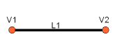 L1 = Part.LineSegment(V1,V2)
L2 = Part.LineSegment(V4,V3)
Note that we didn't need to create Vertices.
We could immediately create Part.LineSegments from FreeCAD Vectors.
This is because here we haven't created Edges yet.
A Part.LineSegment (as well as Part.Circle, Part.Arc, Part.Ellipse or Part.BSpline) does not create an Edge, but rather a base geometry on which an Edge will be created.
Edges are always made from such a base geometry, which is stored in its Curve attribute.
So if you have an Edge, doing:
print(Edge.Curve)
will show you what kind of Edge it is, i.e.
if it's based on a line, an arc, etc...
But let's come back to our exercise, and build the arc segments.
For this, we will need a third point, so we can use the convenient Part.Arc, which takes 3 points:
L1 = Part.LineSegment(V1,V2)
L2 = Part.LineSegment(V4,V3)
Note that we didn't need to create Vertices.
We could immediately create Part.LineSegments from FreeCAD Vectors.
This is because here we haven't created Edges yet.
A Part.LineSegment (as well as Part.Circle, Part.Arc, Part.Ellipse or Part.BSpline) does not create an Edge, but rather a base geometry on which an Edge will be created.
Edges are always made from such a base geometry, which is stored in its Curve attribute.
So if you have an Edge, doing:
print(Edge.Curve)
will show you what kind of Edge it is, i.e.
if it's based on a line, an arc, etc...
But let's come back to our exercise, and build the arc segments.
For this, we will need a third point, so we can use the convenient Part.Arc, which takes 3 points:
 VC1 = FreeCAD.Vector(-10,0,0)
C1 = Part.Arc(V1,VC1,V4)
VC2 = FreeCAD.Vector(40,0,0)
C2 = Part.Arc(V2,VC2,V3)
Now we have 2 lines (L1 and L2) and 2 arcs (C1 and C2).
We need to turn them into edges:
E1 = Part.Edge(L1)
E2 = Part.Edge(L2)
E3 = Part.Edge(C1)
E4 = Part.Edge(C2)
Alternatively, base geometries also have a toShape() function that do exactly the same thing:
E1 = L1.toShape()
E2 = L2.toShape()
...
Once we have a series of Edges, we can now form a Wire, by giving it a list of Edges.
We do need to take care of the order.
W = Part.Wire([E1,E4,E2,E3])
And we can check if our Wire was correctly understood, and that it is correctly closed:
print( W.isClosed() )
Which will print "True" or "False".
In order to make a Face, we need closed Wires, so it is always a good idea to check that before creating the Face.
Now we can create a Face, by giving it a single Wire (or a list of Wires if we want holes):
F = Part.Face(W)
Then we extrude it:
P = F.extrude(FreeCAD.Vector(0,0,10))
Note that P is already a Solid:
print(P.ShapeType)
This is because when we extrude a single Face, we always get a Solid.
This wouldn't be the case, for example, if we had extruded the Wire instead:
S = W.extrude(FreeCAD.Vector(0,0,10))
print(s.ShapeType)
Which will of course give us a hollow shell, with the top and bottom faces missing.
Now that we have our final Shape, we are anxious to see it on screen! So let's create a generic object, and assign our new Solid to it:
myObj2 = FreeCAD.ActiveDocument.addObject("Part::Feature","My_Strange_Solid")
myObj2.Shape = P
FreeCAD.ActiveDocument.recompute()
Alternatively, the Part module also provides a shortcut that does the above operation quicker (but you cannot choose the name of the object):
Part.show(P)
All of the above, and much more, is explained in detail on the Part Scripting page, together with examples.
Read more:
The Part Workbench
Part scripting
VC1 = FreeCAD.Vector(-10,0,0)
C1 = Part.Arc(V1,VC1,V4)
VC2 = FreeCAD.Vector(40,0,0)
C2 = Part.Arc(V2,VC2,V3)
Now we have 2 lines (L1 and L2) and 2 arcs (C1 and C2).
We need to turn them into edges:
E1 = Part.Edge(L1)
E2 = Part.Edge(L2)
E3 = Part.Edge(C1)
E4 = Part.Edge(C2)
Alternatively, base geometries also have a toShape() function that do exactly the same thing:
E1 = L1.toShape()
E2 = L2.toShape()
...
Once we have a series of Edges, we can now form a Wire, by giving it a list of Edges.
We do need to take care of the order.
W = Part.Wire([E1,E4,E2,E3])
And we can check if our Wire was correctly understood, and that it is correctly closed:
print( W.isClosed() )
Which will print "True" or "False".
In order to make a Face, we need closed Wires, so it is always a good idea to check that before creating the Face.
Now we can create a Face, by giving it a single Wire (or a list of Wires if we want holes):
F = Part.Face(W)
Then we extrude it:
P = F.extrude(FreeCAD.Vector(0,0,10))
Note that P is already a Solid:
print(P.ShapeType)
This is because when we extrude a single Face, we always get a Solid.
This wouldn't be the case, for example, if we had extruded the Wire instead:
S = W.extrude(FreeCAD.Vector(0,0,10))
print(s.ShapeType)
Which will of course give us a hollow shell, with the top and bottom faces missing.
Now that we have our final Shape, we are anxious to see it on screen! So let's create a generic object, and assign our new Solid to it:
myObj2 = FreeCAD.ActiveDocument.addObject("Part::Feature","My_Strange_Solid")
myObj2.Shape = P
FreeCAD.ActiveDocument.recompute()
Alternatively, the Part module also provides a shortcut that does the above operation quicker (but you cannot choose the name of the object):
Part.show(P)
All of the above, and much more, is explained in detail on the Part Scripting page, together with examples.
Read more:
The Part Workbench
Part scripting
 Under the Toolbars tab, create a new custom toolbar in the workbench of your choice (or globally), select your macro and add it to the toolbar:
 That's it, we now have a new toolbar button which, when clicked, will create a parametric rectangle.
Remember, if you want to distribute files created with this new tool to other people, they must have the ParamRectangle.py macro installed on their computer too.
Read more
The FreeCAD macros repository
Parametric object example
More examples in the FreeCAD code
That's it, we now have a new toolbar button which, when clicked, will create a parametric rectangle.
Remember, if you want to distribute files created with this new tool to other people, they must have the ParamRectangle.py macro installed on their computer too.
Read more
The FreeCAD macros repository
Parametric object example
More examples in the FreeCAD code
 Let's start by creating the widget.
Start Qt Creator, then menu File → New File or Project → Files and Classes → Qt → Qt Designer Form → Dialog without buttons.
Click Next, give it a filename to save, click Next, leave all project fields to their default value ("<none>"), and Create.
FreeCAD's Task system will automatically add OK/Cancel buttons, that's why we chose here a dialog without buttons.
Let's start by creating the widget.
Start Qt Creator, then menu File → New File or Project → Files and Classes → Qt → Qt Designer Form → Dialog without buttons.
Click Next, give it a filename to save, click Next, leave all project fields to their default value ("<none>"), and Create.
FreeCAD's Task system will automatically add OK/Cancel buttons, that's why we chose here a dialog without buttons.
 Find the Label in the list in the left panel, and drag it onto the canvas of our widget.
Double-click the recent placed Label, and change its text to Length.
Right-click the widget canvas, and choose Lay out → Lay out in a Grid.
This will turn our widget into a grid with currently only one cell, occupied by ourfirst label.
We can now add the next items at the left, right, top or bottom of our first label, and the grid will expand automatically.
Add two more labels below the first one, and change their text to Width and Height:
Find the Label in the list in the left panel, and drag it onto the canvas of our widget.
Double-click the recent placed Label, and change its text to Length.
Right-click the widget canvas, and choose Lay out → Lay out in a Grid.
This will turn our widget into a grid with currently only one cell, occupied by ourfirst label.
We can now add the next items at the left, right, top or bottom of our first label, and the grid will expand automatically.
Add two more labels below the first one, and change their text to Width and Height:
 Now place 3 Double Spin Box widgets next to our Length, Width and Height labels.
For each of them, in the lower right panel, which shows all the available settings for the selected widget, locate Suffix and set their suffix to mm.
FreeCAD has a more advanced widget, that can handle different units, but that is not available in Qt Creator by default (but can be compiled), so for now we will use a standard Double Spin Box, and we add the "mm" suffix to make sure the user knows in which units they work:
Now place 3 Double Spin Box widgets next to our Length, Width and Height labels.
For each of them, in the lower right panel, which shows all the available settings for the selected widget, locate Suffix and set their suffix to mm.
FreeCAD has a more advanced widget, that can handle different units, but that is not available in Qt Creator by default (but can be compiled), so for now we will use a standard Double Spin Box, and we add the "mm" suffix to make sure the user knows in which units they work:
 Now our widget is done, we just need to make sure of one last thing.
Since FreeCAD will need to access that widget and read the Length, Width and Height values, we need to give proper names to those widgets, so we can easily retrive them from within FreeCAD.
Click each of the Double Spin Boxes, and in the upper right window, double-click their Object Name, and change them to something easy to remember, for example: BoxLength, BoxWidth and BoxHeight:
Now our widget is done, we just need to make sure of one last thing.
Since FreeCAD will need to access that widget and read the Length, Width and Height values, we need to give proper names to those widgets, so we can easily retrive them from within FreeCAD.
Click each of the Double Spin Boxes, and in the upper right window, double-click their Object Name, and change them to something easy to remember, for example: BoxLength, BoxWidth and BoxHeight:
 Save the file, you can now close Qt Creator, the rest will be done in Python.
Open FreeCAD and create a new macro from menu Macro → Macros → Create
Paste the following code.
Make sure you change the file path to match where you saved the .ui file created in QtCreator:
import FreeCAD,FreeCADGui,Part
# CHANGE THE LINE BELOW
path_to_ui = "C:\Users\yorik\Documents\dialog.ui"
class BoxTaskPanel:
def __init__(self):
# this will create a Qt widget from our ui file
self.form = FreeCADGui.PySideUic.loadUi(path_to_ui)
def accept(self):
length = self.form.BoxLength.value()
width = self.form.BoxWidth.value()
height = self.form.BoxHeight.value()
if (length == 0) or (width == 0) or (height == 0):
print("Error! None of the values can be 0!")
# we bail out without doing anything
return
box = Part.makeBox(length,width,height)
Part.show(box)
FreeCADGui.Control.closeDialog()
panel = BoxTaskPanel()
FreeCADGui.Control.showDialog(panel)
In the code above, we used a convenience function (PySideUic.loadUi) from the FreeCADGui module.
That function loads a .ui file, creates a Qt Widget from it, and maps names, so we can easily access the subwidget by their names (ex: self.form.BoxLength).
The "accept" function is also a convenience offered by Qt.
When there is an "OK" button in a dialog (which is the case by default when using the FreeCAD Tasks panel), any function named "accept" will automatically be executed when the "OK" button is pressed.
Similarly, you can also add a "reject" function which gets executed when the "Cancel" button is pressed.
In our case, we omitted that function, so pressing "Cancel" will do the default behaviour (do nothing and close the dialog).
If we implement any of the accept or reject functions, their default behaviour (do nothing and close) will not occur anymore.
So we need to close the Task panel ourselves.
This is done with:
FreeCADGui.Control.closeDialog()
Once we have our BoxTaskPanel that has 1- a widget called "self.form" and 2- if needed, accept and reject functions, we can open the task panel with it, which is done with these two last lines:
panel = BoxTaskPanel()
FreeCADGui.Control.showDialog(panel)
Note that the widget created by PySideUic.loadUi is not specific to FreeCAD, it is a standard Qt widget which can be used with other Qt tools.
For example, we could have shown a separate dialog box with it.
Try this in the Python Console of FreeCAD (using the correct path to your .ui file of course):
from PySide import QtGui
w = FreeCADGui.PySideUic.loadUi("C:\Users\yorik\Documents\dialog.ui")
w.show()
Of course we didn't add any "OK" or "Cancel" button to our dialog, since it was made to be used from the FreeCAD Task panel, which already provides such buttons.
So there is no way to close the dialog (other than pressing its Window Close button).
But the function show() creates a non-modal dialog, which means it doesn't block the rest of the interface.
So, while our dialog is still open, we can read the values of the fields:
w.BoxHeight.value()
This is very useful for testing.
Finally, don't forget there is much more documentation about using Qt widgets on the FreeCAD Wiki, in the Python Scripting section, which contains a dialog creation tutorial, a special 3-part PySide tutorial that covers the subject extensively.
Save the file, you can now close Qt Creator, the rest will be done in Python.
Open FreeCAD and create a new macro from menu Macro → Macros → Create
Paste the following code.
Make sure you change the file path to match where you saved the .ui file created in QtCreator:
import FreeCAD,FreeCADGui,Part
# CHANGE THE LINE BELOW
path_to_ui = "C:\Users\yorik\Documents\dialog.ui"
class BoxTaskPanel:
def __init__(self):
# this will create a Qt widget from our ui file
self.form = FreeCADGui.PySideUic.loadUi(path_to_ui)
def accept(self):
length = self.form.BoxLength.value()
width = self.form.BoxWidth.value()
height = self.form.BoxHeight.value()
if (length == 0) or (width == 0) or (height == 0):
print("Error! None of the values can be 0!")
# we bail out without doing anything
return
box = Part.makeBox(length,width,height)
Part.show(box)
FreeCADGui.Control.closeDialog()
panel = BoxTaskPanel()
FreeCADGui.Control.showDialog(panel)
In the code above, we used a convenience function (PySideUic.loadUi) from the FreeCADGui module.
That function loads a .ui file, creates a Qt Widget from it, and maps names, so we can easily access the subwidget by their names (ex: self.form.BoxLength).
The "accept" function is also a convenience offered by Qt.
When there is an "OK" button in a dialog (which is the case by default when using the FreeCAD Tasks panel), any function named "accept" will automatically be executed when the "OK" button is pressed.
Similarly, you can also add a "reject" function which gets executed when the "Cancel" button is pressed.
In our case, we omitted that function, so pressing "Cancel" will do the default behaviour (do nothing and close the dialog).
If we implement any of the accept or reject functions, their default behaviour (do nothing and close) will not occur anymore.
So we need to close the Task panel ourselves.
This is done with:
FreeCADGui.Control.closeDialog()
Once we have our BoxTaskPanel that has 1- a widget called "self.form" and 2- if needed, accept and reject functions, we can open the task panel with it, which is done with these two last lines:
panel = BoxTaskPanel()
FreeCADGui.Control.showDialog(panel)
Note that the widget created by PySideUic.loadUi is not specific to FreeCAD, it is a standard Qt widget which can be used with other Qt tools.
For example, we could have shown a separate dialog box with it.
Try this in the Python Console of FreeCAD (using the correct path to your .ui file of course):
from PySide import QtGui
w = FreeCADGui.PySideUic.loadUi("C:\Users\yorik\Documents\dialog.ui")
w.show()
Of course we didn't add any "OK" or "Cancel" button to our dialog, since it was made to be used from the FreeCAD Task panel, which already provides such buttons.
So there is no way to close the dialog (other than pressing its Window Close button).
But the function show() creates a non-modal dialog, which means it doesn't block the rest of the interface.
So, while our dialog is still open, we can read the values of the fields:
w.BoxHeight.value()
This is very useful for testing.
Finally, don't forget there is much more documentation about using Qt widgets on the FreeCAD Wiki, in the Python Scripting section, which contains a dialog creation tutorial, a special 3-part PySide tutorial that covers the subject extensively.


 Rebar tools: the Reinforcement Addon augments the Arch Workbench Structures.
 Straight Rebar: creates a Straight reinforcement bar in a selected structural element.
 UShape Rebar: creates a UShape reinforcement bar in a selected structural element.
 LShape Rebar: creates a LShape reinforcement bar in a selected structural element.
 Bent Shape Rebar: creates a Bent Shape reinforcement bar in a selected structural element.
 Stirrup Rebar: creates a Stirrup reinforcement bar in a selected structural element.
 Helical Rebar: creates a Helical reinforcement bar in a selected structural element.
 ColumnReinforcement: creates a reinforcing bars inside a Column Arch Structure object.
 BeamReinforcement: creates reinforcing bars inside a Beam Arch Structure object.
 Building Part: Creates a building part including selected objects
 Axis tools: The Axis tool allows you to places a series of axes in the current document.
 Panel tools: Allows you to build all kinds of panel-like elements.
 Pipe tools introduced in version 0.17
 Material tools: The Material tools allows to add materials to the active document.
 The image shows the grid aligned with the XY plane.


 AutoGroup: changes the active Draft Layer or, optionally, the active Std Group or group-like Arch object.


 Workflow of the FEM Workbench; the workbench calls two external programs to perform meshing of a solid object, and perform the actual solution of the finite element problem


 The Part Workbench is the basic layer that exposes the OCCT drawing functions to all workbenches in FreeCAD.
 Offset tools:
 Compound Tools:
 Join features:
 Splitting tools:
 Measure: Tools for linear and angular measurements.

 Create an additive primitive: adds an additive primitive to the active body.
 Create a subtractive primitive: adds a subtractive primitive to the active body.
 The FreeCAD Path Workbench workflow creates these machine instructions as follows:
A 3D model is the base object, typically created using one or more of the
The FreeCAD Path Workbench workflow creates these machine instructions as follows:
A 3D model is the base object, typically created using one or more of the
 Visual reference for Depth properties (settings)
 Raytracing workbench icon


 You will be asked for a location to save the resulting *.pov file.
After that you can open it in Povray and render:
You will be asked for a location to save the resulting *.pov file.
After that you can open it in Povray and render:
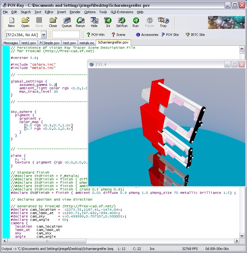 As usual in a renderer you can make big and nice pictures:

 Robot workbench icon
The
Robot workbench icon
The

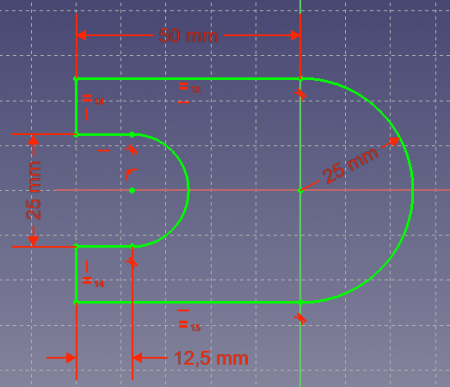 A fully constrained sketch
 Create an arc: This is an icon menu in the Sketcher toolbar that holds the following commands:
 Create a circle: This is an icon menu in the Sketcher toolbar that holds the following commands:
 Create a conic: The sketcher provides the following conical sections.
Unlike B-splines they can be used with all sorts of constraints such as Tangent, Point On Object, or Perpendicular.
Create a conic: The sketcher provides the following conical sections.
Unlike B-splines they can be used with all sorts of constraints such as Tangent, Point On Object, or Perpendicular.
 Create a B-spline: This is an icon menu in the Sketcher toolbar that holds the following commands:
 Create rectangles: This is an icon menu in the Sketcher toolbar that holds the following commands: introduced in version 0.20
 Create regular polygon: This is an icon menu in the Sketcher toolbar that holds the following commands:
 A spreadsheet with certain cells filled with text and quantities
 As indicated by the tabs, the following properties can be changed:
Color: Text color and background color
Alignment: Text horizontal and vertical alignment
Style: Text style: bold, italic, underline
Units: Display units for this cell.
Please read the Units section below.
Alias: Define an alias for this cell.
This alias can be used in cell formulas and also in general expressions; see section Spreadsheet data in expressions for more information.
As indicated by the tabs, the following properties can be changed:
Color: Text color and background color
Alignment: Text horizontal and vertical alignment
Style: Text style: bold, italic, underline
Units: Display units for this cell.
Please read the Units section below.
Alias: Define an alias for this cell.
This alias can be used in cell formulas and also in general expressions; see section Spreadsheet data in expressions for more information.


 The FreeCAD Python console
If you don't see it, click on View → Panels → Python console.
The Python console can be resized and also undocked.
The interpreter shows the Python version, then a
The FreeCAD Python console
If you don't see it, click on View → Panels → Python console.
The Python console can be resized and also undocked.
The interpreter shows the Python version, then a 

 .
On it you have 4 buttons: Record, stop recording, edit and play the current macro.
It is very simple to use: Press the record button, you will be asked to give a name to your macro, then perform some actions.
When you are done, click the stop recording button, and your actions will be saved.
You can now access the macro dialog with the edit button.
.
On it you have 4 buttons: Record, stop recording, edit and play the current macro.
It is very simple to use: Press the record button, you will be asked to give a name to your macro, then perform some actions.
When you are done, click the stop recording button, and your actions will be saved.
You can now access the macro dialog with the edit button.
 Macro dialog, listing the macros available in the system
There you can manage your macros, delete, edit, duplicate, install or create new ones from scratch.
If you edit a macro, it will be opened in an editor window where you can make changes to its code.
New macros can be installed using the Addons...
button, which links to the Addon Manager.
Macro dialog, listing the macros available in the system
There you can manage your macros, delete, edit, duplicate, install or create new ones from scratch.
If you edit a macro, it will be opened in an editor window where you can make changes to its code.
New macros can be installed using the Addons...
button, which links to the Addon Manager.
 This way you can make your macro become a real tool, just like any standard FreeCAD tool.
This, added to the power of python scripting within FreeCAD, makes it possible to easily add your own tools to the interface.
See Customize Toolbars for a more detailed description.
This way you can make your macro become a real tool, just like any standard FreeCAD tool.
This, added to the power of python scripting within FreeCAD, makes it possible to easily add your own tools to the interface.
See Customize Toolbars for a more detailed description.


 Image taken from Inventor mentor
An openInventor scenegraph describes everything that is part of a 3D scene, such as geometry, colors, materials, lights, etc, and organizes all that data in a convenient and clear structure.
Everything can be grouped into sub-structures, allowing you to organize your scene contents pretty much the way you like.
Here is an example of an openInventor file:
#Inventor V2.0 ascii
Separator {
RotationXYZ {
axis Z
angle 0
}
Transform {
translation 0 0 0.5
}
Separator {
Material {
diffuseColor 0.05 0.05 0.05
}
Transform {
rotation 1 0 0 1.5708
scaleFactor 0.2 0.5 0.2
}
Cylinder {
}
}
}
As you can see, the structure is very simple.
You use separators to organize your data into blocks, a bit like you would organize your files into folders.
Each statement affects what comes next, for example the first two items of our root separator are a rotation and a translation, both will affect the next item, which is a separator.
In that separator a material is defined and another transformation.
Our cylinder will therefore be affected by both transformations, the one applied directly to it and the one that was applied to its parent separator.
We also have many other types of elements to organize our scene, such as groups, switches or annotations.
We can define very complex materials for our objects, with colors, textures, shading modes and transparency.
We can also define lights, cameras, and even movement.
It is even possible to embed pieces of scripting in openInventor files to define more complex behaviors.
If you are interested in learning more about openInventor head directly to its most famous reference: the Inventor mentor.
In FreeCAD, normally, we don't need to interact directly with the openInventor scenegraph.
Every object in a FreeCAD document, being a mesh, a part shape or anything else, gets automatically converted to openInventor code and inserted in the main scenegraph that you see in a 3D view.
That scenegraph gets updated continuously when you modify, add or remove objects.
In fact every object (in App space) has a view provider (a corresponding object in Gui space) responsible for issuing openInventor code.
But there are many advantages to being able to access the scenegraph directly.
For example, we can temporarily change the appearance of an object, or we can add objects to the scene that have no real existence in the FreeCAD document, such as construction geometry, helpers, graphical hints or tools such as manipulators or on-screen information.
FreeCAD itself features several tools to see or modify openInventor code.
For example, the following python code will show the openInventor representation of a selected object:
obj = FreeCAD.ActiveDocument.ActiveObject
viewprovider = obj.ViewObject
print viewprovider.toString()
But we also have a python module that allows complete access to anything managed by Coin3D, such as our FreeCAD scenegraph.
So, read on to Pivy.
Image taken from Inventor mentor
An openInventor scenegraph describes everything that is part of a 3D scene, such as geometry, colors, materials, lights, etc, and organizes all that data in a convenient and clear structure.
Everything can be grouped into sub-structures, allowing you to organize your scene contents pretty much the way you like.
Here is an example of an openInventor file:
#Inventor V2.0 ascii
Separator {
RotationXYZ {
axis Z
angle 0
}
Transform {
translation 0 0 0.5
}
Separator {
Material {
diffuseColor 0.05 0.05 0.05
}
Transform {
rotation 1 0 0 1.5708
scaleFactor 0.2 0.5 0.2
}
Cylinder {
}
}
}
As you can see, the structure is very simple.
You use separators to organize your data into blocks, a bit like you would organize your files into folders.
Each statement affects what comes next, for example the first two items of our root separator are a rotation and a translation, both will affect the next item, which is a separator.
In that separator a material is defined and another transformation.
Our cylinder will therefore be affected by both transformations, the one applied directly to it and the one that was applied to its parent separator.
We also have many other types of elements to organize our scene, such as groups, switches or annotations.
We can define very complex materials for our objects, with colors, textures, shading modes and transparency.
We can also define lights, cameras, and even movement.
It is even possible to embed pieces of scripting in openInventor files to define more complex behaviors.
If you are interested in learning more about openInventor head directly to its most famous reference: the Inventor mentor.
In FreeCAD, normally, we don't need to interact directly with the openInventor scenegraph.
Every object in a FreeCAD document, being a mesh, a part shape or anything else, gets automatically converted to openInventor code and inserted in the main scenegraph that you see in a 3D view.
That scenegraph gets updated continuously when you modify, add or remove objects.
In fact every object (in App space) has a view provider (a corresponding object in Gui space) responsible for issuing openInventor code.
But there are many advantages to being able to access the scenegraph directly.
For example, we can temporarily change the appearance of an object, or we can add objects to the scene that have no real existence in the FreeCAD document, such as construction geometry, helpers, graphical hints or tools such as manipulators or on-screen information.
FreeCAD itself features several tools to see or modify openInventor code.
For example, the following python code will show the openInventor representation of a selected object:
obj = FreeCAD.ActiveDocument.ActiveObject
viewprovider = obj.ViewObject
print viewprovider.toString()
But we also have a python module that allows complete access to anything managed by Coin3D, such as our FreeCAD scenegraph.
So, read on to Pivy.

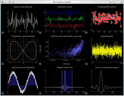 Examples created with PySide.
Left: a simple dialog.
Right: a more complex dialog with graphs.
Examples created with PySide.
Left: a simple dialog.
Right: a more complex dialog with graphs.
 The standard FreeCAD interface
See a full explanation in Interface.
1.
The main view area, which can contain different tabbed windows, principally the 3D view.
2.
The 3D view, showing the geometrical objects in the document.
3.
The tree view (part of the combo view), showing the hierarchy and construction history of objects in the document; it can also display the task panel for active commands.
4.
The property editor (part of the combo view), which allows viewing and modifying properties of the selected objects.
5.
The selection view, which indicates the objects or sub-elements of objects (vertices, edges, faces) that are selected.
6.
The report view (or output window), where messages, warnings and errors are shown.
7.
The Python console, where all the commands executed are printed, and where you can enter Python code.
8.
The status bar, where some messages and tooltips appear.
9.
The toolbar area, where the toolbars are docked.
10.
The workbench selector, where you select the active workbench.
11.
The standard menu, which holds basic operations of the program.
The main concept behind the FreeCAD interface is that it is separated into workbenches.
A workbench is a collection of tools suited for a specific task, such as working with meshes, or drawing 2D objects, or constrained sketches.
You can switch the current workbench with the workbench selector.
You can customize the tools included in each workbench, add tools from other workbenches or even self-created tools, that we call macros.
Widely used starting points are the PartDesign Workbench and Part Workbench.
When you start FreeCAD for the first time, you are presented with the Start page.
Here is what it looks like for version 0.19:
The standard FreeCAD interface
See a full explanation in Interface.
1.
The main view area, which can contain different tabbed windows, principally the 3D view.
2.
The 3D view, showing the geometrical objects in the document.
3.
The tree view (part of the combo view), showing the hierarchy and construction history of objects in the document; it can also display the task panel for active commands.
4.
The property editor (part of the combo view), which allows viewing and modifying properties of the selected objects.
5.
The selection view, which indicates the objects or sub-elements of objects (vertices, edges, faces) that are selected.
6.
The report view (or output window), where messages, warnings and errors are shown.
7.
The Python console, where all the commands executed are printed, and where you can enter Python code.
8.
The status bar, where some messages and tooltips appear.
9.
The toolbar area, where the toolbars are docked.
10.
The workbench selector, where you select the active workbench.
11.
The standard menu, which holds basic operations of the program.
The main concept behind the FreeCAD interface is that it is separated into workbenches.
A workbench is a collection of tools suited for a specific task, such as working with meshes, or drawing 2D objects, or constrained sketches.
You can switch the current workbench with the workbench selector.
You can customize the tools included in each workbench, add tools from other workbenches or even self-created tools, that we call macros.
Widely used starting points are the PartDesign Workbench and Part Workbench.
When you start FreeCAD for the first time, you are presented with the Start page.
Here is what it looks like for version 0.19:
 The Start page allows you to quickly jump to one of the most common workbenches, open one of the recent files, or see the latest news from the FreeCAD world.
You can change the default workbench in the preferences.
The Start page allows you to quickly jump to one of the most common workbenches, open one of the recent files, or see the latest news from the FreeCAD world.
You can change the default workbench in the preferences.
 At any moment, you can select the original sketches and modify them, or change the extrusion parameters of the pad or pocket operations, which will update the final object.
 More on the Tutorials page.
 The cool thing with Lego pieces is that the dimensions are easy to obtain on the Internet, at least for the standard pieces.
These are pretty easy to model and print on a 3D printer, and with a bit of patience (3D printing often requires much adjustment and fine-tuning) you can make pieces that are totally compatible and click perfectly into original Lego blocks.
In the example below, we will make a piece that is 1.5 times bigger than the original.
We will now use exclusively the Sketcher and PartDesign tools.
Since all the tools from the Sketcher Workbench are also included in the Part Design Workbench, we can stay in Part Design and we will not need to switch back and forth between the two.
Part Design objects are fully based on Sketches.
A Sketch is a 2D object, made of linear segments (lines, arcs of circle or ellipses) and constraints.
These constraints can be applied either on linear segments or on their endpoints or center points, and will force the geometry to adopt certain rules.
For example, you can place a vertical constraint on a line segment to force it to stay vertical, or a position (lock) constraint on an endpoint to prohibit it to move.
When a sketch has an exact amount of constraints that prohibits any point of the sketch to be moved anymore, we talk about a fully constrained sketch.
When there are redundant constraints, that could be removed without allowing the geometry to be moved, it is called over-constrained.
This should be avoided, and FreeCAD will notify you if such a case occurs.
Sketches have an edit mode, where their geometry and constraints can be changed.
When you are done with editing, and leave edit mode, sketches behave like any other FreeCAD object, and can be used as building blocks for all the Part Design tools, but also in other workbenches, such as Part or Arch.
The Draft workbench also has a tool that converts Draft objects to Sketches, and vice-versa.
Let's start by modeling a cubic shape that will be the base of our Lego brick.
Later on we will carve the insides, and add the 8 dots on top of it.
So let's start this by making a rectangular sketch that we will then extrude:
Switch to the PartDesign Workbench
Click on the
The cool thing with Lego pieces is that the dimensions are easy to obtain on the Internet, at least for the standard pieces.
These are pretty easy to model and print on a 3D printer, and with a bit of patience (3D printing often requires much adjustment and fine-tuning) you can make pieces that are totally compatible and click perfectly into original Lego blocks.
In the example below, we will make a piece that is 1.5 times bigger than the original.
We will now use exclusively the Sketcher and PartDesign tools.
Since all the tools from the Sketcher Workbench are also included in the Part Design Workbench, we can stay in Part Design and we will not need to switch back and forth between the two.
Part Design objects are fully based on Sketches.
A Sketch is a 2D object, made of linear segments (lines, arcs of circle or ellipses) and constraints.
These constraints can be applied either on linear segments or on their endpoints or center points, and will force the geometry to adopt certain rules.
For example, you can place a vertical constraint on a line segment to force it to stay vertical, or a position (lock) constraint on an endpoint to prohibit it to move.
When a sketch has an exact amount of constraints that prohibits any point of the sketch to be moved anymore, we talk about a fully constrained sketch.
When there are redundant constraints, that could be removed without allowing the geometry to be moved, it is called over-constrained.
This should be avoided, and FreeCAD will notify you if such a case occurs.
Sketches have an edit mode, where their geometry and constraints can be changed.
When you are done with editing, and leave edit mode, sketches behave like any other FreeCAD object, and can be used as building blocks for all the Part Design tools, but also in other workbenches, such as Part or Arch.
The Draft workbench also has a tool that converts Draft objects to Sketches, and vice-versa.
Let's start by modeling a cubic shape that will be the base of our Lego brick.
Later on we will carve the insides, and add the 8 dots on top of it.
So let's start this by making a rectangular sketch that we will then extrude:
Switch to the PartDesign Workbench
Click on the  Now, let's add three more constraints:
Select one of the vertical segments and add a
Now, let's add three more constraints:
Select one of the vertical segments and add a  Note that the last point-on-point constraint was not absolutely necessary.
You are never forced to work with fully constrained sketches.
However, if we are going to print this block in 3D, it will be necessary to maintain our piece close to the origin point (which will be the center of the space where the printer head can move).
By adding that constraint we are making sure that our piece will always stay "anchored" to that origin point.
Our base sketch is now ready, we can leave edit mode by pressing the Close button on top of its task panel, or simply by pressing the Escape key.
If needed later on, we can reenter edit mode anytime by double-clicking the sketch in the tree view.
Let's extrude it by using the
Note that the last point-on-point constraint was not absolutely necessary.
You are never forced to work with fully constrained sketches.
However, if we are going to print this block in 3D, it will be necessary to maintain our piece close to the origin point (which will be the center of the space where the printer head can move).
By adding that constraint we are making sure that our piece will always stay "anchored" to that origin point.
Our base sketch is now ready, we can leave edit mode by pressing the Close button on top of its task panel, or simply by pressing the Escape key.
If needed later on, we can reenter edit mode anytime by double-clicking the sketch in the tree view.
Let's extrude it by using the  The Pad behaves very much like the Extrude tool that we used in the previous chapter.
There are a couple of differences, though, the main one being that a pad cannot be moved.
It is attached forever to its sketch.
If you want to change the position of the pad, you must move the base sketch.
In the current context, where we want to be sure nothing will move out of position, this is an additional security.
We will now carve the inside of the block, using the
The Pad behaves very much like the Extrude tool that we used in the previous chapter.
There are a couple of differences, though, the main one being that a pad cannot be moved.
It is attached forever to its sketch.
If you want to change the position of the pad, you must move the base sketch.
In the current context, where we want to be sure nothing will move out of position, this is an additional security.
We will now carve the inside of the block, using the  We will now constrain the rectangle in relation to the bottom face.
To do this, we need to "import" some edges of the face with the
We will now constrain the rectangle in relation to the bottom face.
To do this, we need to "import" some edges of the face with the  You will notice that only edges from the base face can be added by this tool.
When you create a sketch with a face selected, a relation is created between that face and the sketch, which is important for further operations.
You can always remap a sketch to another face later with the
You will notice that only edges from the base face can be added by this tool.
When you create a sketch with a face selected, a relation is created between that face and the sketch, which is important for further operations.
You can always remap a sketch to another face later with the  Leave edit mode and we can now perform the pocket operation: With the sketch selected, press the
  We will now attack the 8 dots on the top face.
To do this, since they are a repetition of a same feature, we will use the handy
We will now attack the 8 dots on the top face.
To do this, since they are a repetition of a same feature, we will use the handy  Radius Constraint of 3.6mm to each of them
Import the left edge of the base face with the
Radius Constraint of 3.6mm to each of them
Import the left edge of the base face with the  Notice how, once again, when you lock the position and dimension of everything in your sketch, it becomes fully constrained.
This always keeps you on the safe side.
You could change the first sketch now, everything we did afterwards would keep tight.
Leave edit mode, select this new sketch, and create a
Notice how, once again, when you lock the position and dimension of everything in your sketch, it becomes fully constrained.
This always keeps you on the safe side.
You could change the first sketch now, everything we did afterwards would keep tight.
Leave edit mode, select this new sketch, and create a  Notice that, as earlier with the pocket, since we used the top face of our base block as a base for this latest sketch, any PartDesign operation we do with this sketch will correctly be built on top of the base shape: The two dots are not independent objects, they have been extruded directly from our brick.
This is the great advantage of working with the Part Design Workbench, as long as you take care of always building one step on top of the previous one, you are actually building one final solid object.
We can now duplicate our two dots four times, so we get eight.
Select the latest Pad we just created.
Press the
Notice that, as earlier with the pocket, since we used the top face of our base block as a base for this latest sketch, any PartDesign operation we do with this sketch will correctly be built on top of the base shape: The two dots are not independent objects, they have been extruded directly from our brick.
This is the great advantage of working with the Part Design Workbench, as long as you take care of always building one step on top of the previous one, you are actually building one final solid object.
We can now duplicate our two dots four times, so we get eight.
Select the latest Pad we just created.
Press the  Once again, see that this is not just a duplication of an object, it is a *feature* of our shape that has been duplicated, the final object is still only one solid object.
Now let's work on the three "tubes" that fill the void we created on the bottom face.
We have several possibilities: create a sketch with three circles, pad it then pocket it three times, or create a base sketch with one circle inside the other and pad it to form the complete tube already, or even other combinations.
Like always in FreeCAD, there are many ways to achieve the same result.
Sometimes one way will not work the way we want, and we must try other ways.
Here, we will take the safest approach, and do things one step at a time.
Select the face that is at the bottom of the hollow space we carved earlier inside the block.
Create a new sketch, add a circle with a radius of 4.8825mm, import the left border of the face, and constrain it vertically and horizontally at 10.2mm from the upper corner of the face:
Once again, see that this is not just a duplication of an object, it is a *feature* of our shape that has been duplicated, the final object is still only one solid object.
Now let's work on the three "tubes" that fill the void we created on the bottom face.
We have several possibilities: create a sketch with three circles, pad it then pocket it three times, or create a base sketch with one circle inside the other and pad it to form the complete tube already, or even other combinations.
Like always in FreeCAD, there are many ways to achieve the same result.
Sometimes one way will not work the way we want, and we must try other ways.
Here, we will take the safest approach, and do things one step at a time.
Select the face that is at the bottom of the hollow space we carved earlier inside the block.
Create a new sketch, add a circle with a radius of 4.8825mm, import the left border of the face, and constrain it vertically and horizontally at 10.2mm from the upper corner of the face:
 If you have trouble to select features hiding part of the model can help.
To hide a feature select it from tree view and press Space-key to toggle visibility.
Leave edit mode, and pad this sketch with a distance of 12.6mm
Create a linear pattern from this last pad, give it a length of 24mm and 3 occurrences.
We now have three filled tubes filling the hollow space:
If you have trouble to select features hiding part of the model can help.
To hide a feature select it from tree view and press Space-key to toggle visibility.
Leave edit mode, and pad this sketch with a distance of 12.6mm
Create a linear pattern from this last pad, give it a length of 24mm and 3 occurrences.
We now have three filled tubes filling the hollow space:
 Now let's make the final holes.
Select the circular face of the first of our three "pins"
Create a new sketch, import the circular border of our face, create a circle with a radius constraint of 3.6mm, and add a
Now let's make the final holes.
Select the circular face of the first of our three "pins"
Create a new sketch, import the circular border of our face, create a circle with a radius constraint of 3.6mm, and add a  Leave edit mode, and create a pocket from this sketch, with a length of 12.6mm
Create a linear pattern from this pocket, with a length of 24mm and 3 occurrences.
That's the last step, our piece of lego is now complete, so we can give it a nice color to mark our victory!
Leave edit mode, and create a pocket from this sketch, with a length of 12.6mm
Create a linear pattern from this pocket, with a length of 24mm and 3 occurrences.
That's the last step, our piece of lego is now complete, so we can give it a nice color to mark our victory!
 You will notice that our modeling history (what appears in the tree view) has become quite long.
This is precious because every single step of what we did can be changed later on.
Adapting this model for another kind of brick, for example one with 2x2 dots, instead of 2x4, would be a piece of cake, we would just need to change a couple of dimensions and the number of occurrences in linear patterns.
We could as easily create bigger pieces that don't exist in the original Lego game.
But we could also want to get rid of the history, for example if we are going to model a castle with this brick, and we don't want to have this whole history repeated 500 times in our file.
There are two simple ways to get rid of the history, one is using the Create simple copy tool from the Part Workbench, which will create a copy of our piece that doesn't depend anymore on the history (you can delete the whole history afterwards), the other way is exporting the piece as a STEP file and reimporting it.
Assembling
But the best of both worlds also exists, which is the Assembly2 Workbench, an addon that can be installed from the FreeCAD-addons repository.
This Workbench is named "2" because there is also an official built-in Assembly Workbench in development, which is not ready yet.
The Assembly2 Workbench, however, already works very well to construct assemblies, and also features a couple of object-to-object constraints which you can use to constrain the position of one object in relation to another.
In the example below, however, it will be quicker and easier to position the pieces using
You will notice that our modeling history (what appears in the tree view) has become quite long.
This is precious because every single step of what we did can be changed later on.
Adapting this model for another kind of brick, for example one with 2x2 dots, instead of 2x4, would be a piece of cake, we would just need to change a couple of dimensions and the number of occurrences in linear patterns.
We could as easily create bigger pieces that don't exist in the original Lego game.
But we could also want to get rid of the history, for example if we are going to model a castle with this brick, and we don't want to have this whole history repeated 500 times in our file.
There are two simple ways to get rid of the history, one is using the Create simple copy tool from the Part Workbench, which will create a copy of our piece that doesn't depend anymore on the history (you can delete the whole history afterwards), the other way is exporting the piece as a STEP file and reimporting it.
Assembling
But the best of both worlds also exists, which is the Assembly2 Workbench, an addon that can be installed from the FreeCAD-addons repository.
This Workbench is named "2" because there is also an official built-in Assembly Workbench in development, which is not ready yet.
The Assembly2 Workbench, however, already works very well to construct assemblies, and also features a couple of object-to-object constraints which you can use to constrain the position of one object in relation to another.
In the example below, however, it will be quicker and easier to position the pieces using  Downloads
The model produced during this exercise: https://github.com/yorikvanhavre/FreeCAD-manual/blob/master/files/lego.FCStd
Read more
The Sketcher
The Part Design Workbench
The Assembly2 Workbench
Downloads
The model produced during this exercise: https://github.com/yorikvanhavre/FreeCAD-manual/blob/master/files/lego.FCStd
Read more
The Sketcher
The Part Design Workbench
The Assembly2 Workbench


 On the left: cross-sections (A) and (B) to be swept along path (C); resulting Additive pipe on the right.
 A solid sweep generated from a single profile (A) projected along a path (B).
 The "Frenet" property controls how the profile orientation changes as it follows along the sweep path.
If "Frenet" is "false", the orientation of the profile is kept consistent from point to point.
The resulting shape has the minimum possible twisting.
Unintuitively, when a profile is swept along a helix, this results in the orientation of the profile slowly creep (rotate) as it follows the helix.
Setting "Frenet" to true prevents such a creep.
If "Frenet" is "true" the orientation of the profile is computed basing on local curvature and tangency vectors of the path.
This keeps the orientation of the profile consistent when sweeping along a helix (because curvature vector of a straight helix is always pointing to its axis).
However, when path is not a helix, the resulting shape can have strange looking twists sometimes.
For more information, see Frenet Serret formulas.
The "Frenet" property controls how the profile orientation changes as it follows along the sweep path.
If "Frenet" is "false", the orientation of the profile is kept consistent from point to point.
The resulting shape has the minimum possible twisting.
Unintuitively, when a profile is swept along a helix, this results in the orientation of the profile slowly creep (rotate) as it follows the helix.
Setting "Frenet" to true prevents such a creep.
If "Frenet" is "true" the orientation of the profile is computed basing on local curvature and tangency vectors of the path.
This keeps the orientation of the profile consistent when sweeping along a helix (because curvature vector of a straight helix is always pointing to its axis).
However, when path is not a helix, the resulting shape can have strange looking twists sometimes.
For more information, see Frenet Serret formulas.

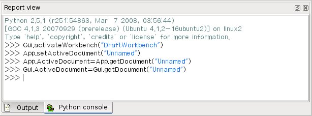 The FreeCAD Python console
In this tutorial you can use both methods.
You can copy-paste each line in the Python console and then press Enter, or copy-paste the entire code in a new Macro window.
The FreeCAD Python console
In this tutorial you can use both methods.
You can copy-paste each line in the Python console and then press Enter, or copy-paste the entire code in a new Macro window.
 The autocomplete mechanism of the FreeCAD Python console
Now our new document will be created.
This is similar to pressing the
The autocomplete mechanism of the FreeCAD Python console
Now our new document will be created.
This is similar to pressing the  Test Cube
 cube and cylinder


 This tutorial aims to teach FreeCAD beginners a few basic features through an example.
After covering the basics in the User hub, you will be able to model a first part step by step.
We will cover in this tutorial in particular:
Using Part Design workbench, tracing the sketch.
Using Pad and Pocket features.
Changing color and transparency.
Moving the part manually.
Displaying reference dimensions in the sketch.
Editing one or more dimensions.
Using external geometry feature and using a reference plane to centre a hole.
This tutorial aims to teach FreeCAD beginners a few basic features through an example.
After covering the basics in the User hub, you will be able to model a first part step by step.
We will cover in this tutorial in particular:
Using Part Design workbench, tracing the sketch.
Using Pad and Pocket features.
Changing color and transparency.
Moving the part manually.
Displaying reference dimensions in the sketch.
Editing one or more dimensions.
Using external geometry feature and using a reference plane to centre a hole.
 The newly created active Body with its content expanded.
The Origin is greyed out, which indicates that its content is not visible in the 3D view.
You can make Origin's content visible in the 3D view by selecting Origin and pressing the spacebar on your keyboard.
Origin will now show black in the tree.
Press the spacebar again to hide its content in the 3D view.
Click again on the arrow or plus sign in front of Origin to collapse its content in the Model tree.
Before we continue, let's take the opportunity to rename the Body.
Rename body:
In the Model tree, click on the Body with the right mouse button.
Select Rename and type a name, for example "Body part1" and press Enter to validate.
Create sketch:
We will now trace the sketch which defines the general shape of the part.
A sketch is a diagram describing a profile to be applied to a feature in order to produce a shape.
It can be either "positive" or "additive", like a pad for example; or "negative" or "subtractive", like a pocket.
Here, since the part's general shape is regular along the Y axis, we will create the Pad along this axis.
Press
The newly created active Body with its content expanded.
The Origin is greyed out, which indicates that its content is not visible in the 3D view.
You can make Origin's content visible in the 3D view by selecting Origin and pressing the spacebar on your keyboard.
Origin will now show black in the tree.
Press the spacebar again to hide its content in the 3D view.
Click again on the arrow or plus sign in front of Origin to collapse its content in the Model tree.
Before we continue, let's take the opportunity to rename the Body.
Rename body:
In the Model tree, click on the Body with the right mouse button.
Select Rename and type a name, for example "Body part1" and press Enter to validate.
Create sketch:
We will now trace the sketch which defines the general shape of the part.
A sketch is a diagram describing a profile to be applied to a feature in order to produce a shape.
It can be either "positive" or "additive", like a pad for example; or "negative" or "subtractive", like a pocket.
Here, since the part's general shape is regular along the Y axis, we will create the Pad along this axis.
Press  Let's start with the first segments:
Select the
Let's start with the first segments:
Select the  Note the small red lines above and beside the segments you have drawn: these are horizontal and vertical constraints.
Your lines are forced to stay either horizontal or vertical.
Note also the symbol in the form of a small arc on the left: it means that the point is fixed to the Z axis.
Now pick different line segments with the left mouse button and while keeping the left button pressed, drag the mouse to try to move them: some are free, others not.
Applying constraints:
At the top of the combo box, in the Tasks panel, you can read the number of degrees of freedom of the already sketched elements: it must be about 6, the objective of the constraints is to reduce the number of degrees of freedom to 0.
The slanted line should be free to rotate at this time: we will give it an angle constraint to fix it.
Click on the slanted line, then the bottom line; once selected these lines will turn dark green; then click the
Note the small red lines above and beside the segments you have drawn: these are horizontal and vertical constraints.
Your lines are forced to stay either horizontal or vertical.
Note also the symbol in the form of a small arc on the left: it means that the point is fixed to the Z axis.
Now pick different line segments with the left mouse button and while keeping the left button pressed, drag the mouse to try to move them: some are free, others not.
Applying constraints:
At the top of the combo box, in the Tasks panel, you can read the number of degrees of freedom of the already sketched elements: it must be about 6, the objective of the constraints is to reduce the number of degrees of freedom to 0.
The slanted line should be free to rotate at this time: we will give it an angle constraint to fix it.
Click on the slanted line, then the bottom line; once selected these lines will turn dark green; then click the  Enter a value of 30°.
Both lines have a fixed angle now.
The constraint was created to the left of the sketch; with the mouse, move it inside the profile.
We will now constrain the bottom line with a dimension: select it then click on
Enter a value of 30°.
Both lines have a fixed angle now.
The constraint was created to the left of the sketch; with the mouse, move it inside the profile.
We will now constrain the bottom line with a dimension: select it then click on  Notice that the number of degrees of freedom reduced to 2.
These are the ends still open.
Tracing the arc
Click on
Notice that the number of degrees of freedom reduced to 2.
These are the ends still open.
Tracing the arc
Click on  The sketch has become green, which means that it is fully constrained.
There is no longer any ambiguity, everything is perfectly defined.
This is confirmed by the solver message at the top left.
Also note that the center of the arc has moved slightly, indeed giving these last three constraints, FreeCAD has calculated the true position of the center.
If your sketch is not yet green, one or more points are not coincident (2 points can be superimposed yet not be coincident).
Make a small window (capture window) around a point to select, and create a
The sketch has become green, which means that it is fully constrained.
There is no longer any ambiguity, everything is perfectly defined.
This is confirmed by the solver message at the top left.
Also note that the center of the arc has moved slightly, indeed giving these last three constraints, FreeCAD has calculated the true position of the center.
If your sketch is not yet green, one or more points are not coincident (2 points can be superimposed yet not be coincident).
Make a small window (capture window) around a point to select, and create a  Creating the hole
Click on the top (square) side of the part and click the
Creating the hole
Click on the top (square) side of the part and click the  Close the sketch; in the Model tree, a new Sketch001 object has appeared below Pad.
While Sketch001 is still selected, click on
Close the sketch; in the Model tree, a new Sketch001 object has appeared below Pad.
While Sketch001 is still selected, click on  Click on the three small dots, i.e., the ellipsis (if they don't appear, click on the Value section of the Placement field); this opens a new dialog in the Tasks panel.
Using the arrows you can vary the position and angles of the part.
It is actually the position of the body (so its origin) that moves in space, the orientation of the 3D view does not change.
Another method: in the Combo View, select the Body and click on the right button of the mouse, then select Transform.
A view like this appears:
Click on the three small dots, i.e., the ellipsis (if they don't appear, click on the Value section of the Placement field); this opens a new dialog in the Tasks panel.
Using the arrows you can vary the position and angles of the part.
It is actually the position of the body (so its origin) that moves in space, the orientation of the 3D view does not change.
Another method: in the Combo View, select the Body and click on the right button of the mouse, then select Transform.
A view like this appears:
 Hold and drag the cones along the axes or the spheres to move the body in all directions.
Validate.
Then reset angles and coordinates to 0.
Hold and drag the cones along the axes or the spheres to move the body in all directions.
Validate.
Then reset angles and coordinates to 0.
 We can see for example that the arc has a length of 20 since it's tangent with the edges.
We can also see that FreeCAD calculates the left face (50-50xTAN 30 °), as well as the distance dimension of the axis of the arc with the origin.
We can see for example that the arc has a length of 20 since it's tangent with the edges.
We can also see that FreeCAD calculates the left face (50-50xTAN 30 °), as well as the distance dimension of the axis of the arc with the origin.
 Leave the sketch, we see that the circle is well centred.
(The pocket feature was not deleted, but modified).
If you change the dimensions of the part again, the thickness or the length, the circle will remain centered on the face.
Avoid construction lines:
It is often possible to avoid creating construction lines.
You can edit the sketch again, erase the construction lines and use a
Leave the sketch, we see that the circle is well centred.
(The pocket feature was not deleted, but modified).
If you change the dimensions of the part again, the thickness or the length, the circle will remain centered on the face.
Avoid construction lines:
It is often possible to avoid creating construction lines.
You can edit the sketch again, erase the construction lines and use a  We get exactly the same result for the position of the hole.
In fact, thanks to the constraints available in the Sketcher workbench, there are many possible methods.
This example shows that it is often better to choose the simplest method, thus limiting the number of objects created as well as the errors that might result.
Second method using a datum plane.
Here is another, faster method that is possible since version 0.17: the use of a datum plane and its attachment.
Start by erasing the "Pocket" function as well as the sketch of the hole.
Select the top face and click
We get exactly the same result for the position of the hole.
In fact, thanks to the constraints available in the Sketcher workbench, there are many possible methods.
This example shows that it is often better to choose the simplest method, thus limiting the number of objects created as well as the errors that might result.
Second method using a datum plane.
Here is another, faster method that is possible since version 0.17: the use of a datum plane and its attachment.
Start by erasing the "Pocket" function as well as the sketch of the hole.
Select the top face and click  This tutorial is completed, save this file, you can have fun exploring various features.
Change other dimensions, make other shapes, put other holes on other faces, it is when making mistakes that we progress!
This tutorial is completed, save this file, you can have fun exploring various features.
Change other dimensions, make other shapes, put other holes on other faces, it is when making mistakes that we progress!